Removal and installation
1. Disconnect a wire from the negative plug of the storage battery.
2. Drain engine oil (see chapter "Maintenance and general inspection and adjustment procedures").
3. Remove the bottom guard.
4. Remove the oil pan.
5. Remove the timing belt (see chapter "Engine. Mechanical").
6. Remove the crankshaft pulley.
7. Remove the parts in the order they are numbered in the figure "Removal and installation of the oil pump".
8. Installation of parts during assembly is carried out in the reverse order of removal.
9. Fill the required amount of engine oil into the lubrication system (see chapter "Maintenance and general inspection and adjustment procedures").
10. Start the engine and check for engine oil leakage.
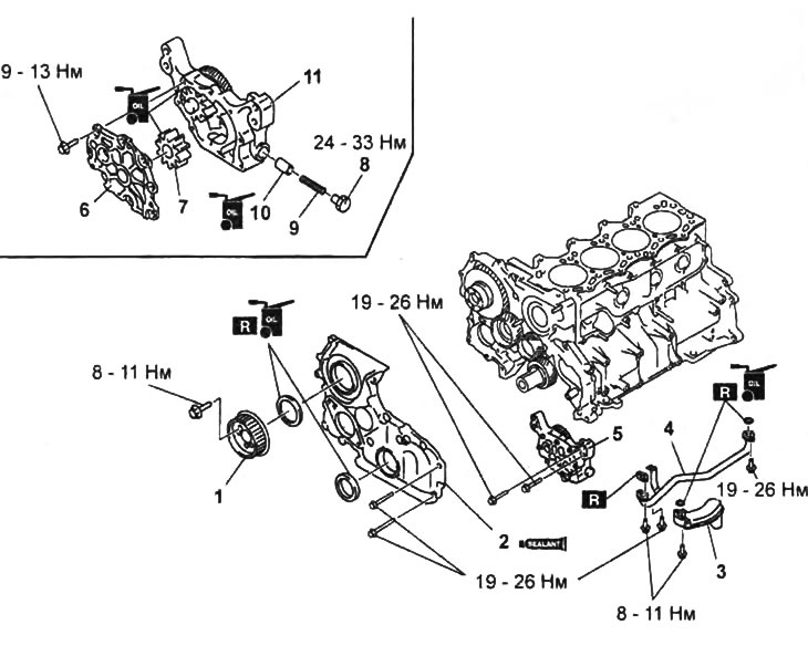
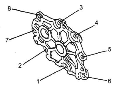
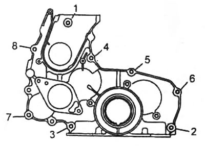
Removal and installation of the oil pump.
1 - injection pump pulley,
2 - front cover of the gear mechanism,
3 - oil receiver,
4 - oil pipe,
5 - oil pump assembly,
6 - oil pump cover,
7 - driven rotor,
8 - plug,
9 - pressure reducing valve spring,
10 - pressure reducing valve,
11 - oil pump housing.
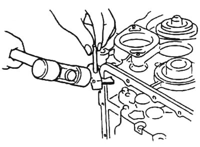
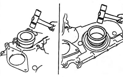
Note on removing the injection pump gear drive cover
1. Using a special separator, cut off the sealant and remove the cover of the high-pressure fuel pump drive gear mechanism.
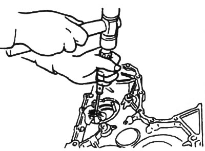
2. Remove the gland of the cover of the gear drive mechanism of the injection pump using a slotted screwdriver wrapped in rags.
Oil Pump Cover Installation Note
Tighten the oil pump cover bolts in several passes in the sequence shown in the figure.
- Tightening torque - 9-13 Nm
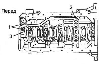
Oil pipe installation note
Tighten the oil pipe mounting bolts in several passes in the sequence shown in the figure.
Note on installing the injection pump gear drive cover
1. Apply a coat of engine oil to the lip of the oil seal.
2. Press in the gland of the cover of the gear mechanism of the injection pump drive using a mandrel of a suitable diameter and a hammer.
- Depth of pressing - 0-0.4 mm
3. Apply silicone sealant to the contact surfaces of the high pressure fuel pump drive gear mechanism cover in the places indicated in the figure.
- Sealant thickness - 2-3 mm
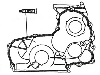
4. Tighten the bolts securing the cover of the gear mechanism of the injection pump drive in two or three passes in the sequence shown in the figure.
Examination
1. Check the oil pump housing and cover for damage and deformation.
2. Check the pressure reducing valve for damage and wear.
3. Check the pressure reducing valve spring for damage or deformation.
4. Using a feeler gauge, measure the radial clearance between the male rotor and pump housing, between the male rotor and pump housing.
- Nominal clearance - 0.10-0.19 mm
- Maximum clearance - 0.20 mm
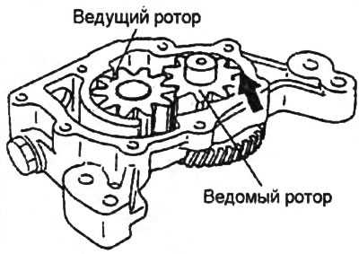
5. Using a precision ruler and feeler gauge, measure the end clearance between the rotors and the surface of the oil pump housing.
- Nominal clearance - 0.04-0.09 mm
- Maximum clearance - 0.15 mm
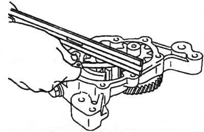
If any of the clearances is greater than the maximum value, replace the rotor and/or oil pump housing.
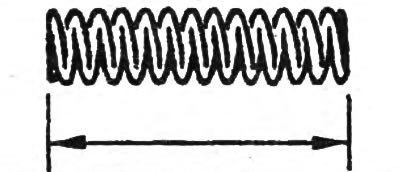
6. Using a caliper, measure the free length of the pressure reducing valve spring. If necessary, replace the spring.
- Spring length - 43.8 mm