


Contents: Removal ⇓ Installation ⇓
Note: Removal of the automatic transmission from the vehicle is not required to remove and install the valve body.
Removal
Attention.
- A hot transmission and automatic transmission fluid can cause various burns. Turn off the engine and wait until the transmission cools down.
- When compressed air is supplied, various contaminants and particles fly out and can get into the eyes. When working with compressed air, use protective glasses.
- If the transmission valve body is replaced with a new one, the initial learning procedure must be performed (see section below in this chapter).
- If you place the valve body with the connector side down on a flat surface, the connector or the valve body sensors may be damaged. When servicing the valve body, place it on a soft material that does not release dust or other foreign particles! Make sure that the connector and valve body sensors do not directly touch the workbench surface.
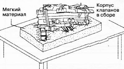
1. Move the selector lever to position P.
2. Disconnect the negative battery terminal.
3. Remove the front protective tray No.2.
4. Thoroughly clean the outside of the gearbox with steam or cleaning agents.
5. Remove the engine air filter assembly.
6. Disconnect the valve body connector.
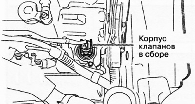
Attention.
- Be careful not to touch the connector terminals with your hands, as this may damage the terminals.
- Water or foreign objects entering the connector may cause poor connection and corrosion. When disconnecting the connector, be careful not to allow water or foreign objects to enter.
7. Remove the hose clamp.
8. Drain the automatic transmission fluid.
9. Remove the automatic transmission oil pan.
Caution. To prevent damage to the valve body, if a large amount of sediment is found in the transmission oil pan when removing it, replace the oil pickup with a new one. If there is no sediment in the transmission oil pan, there is no need to replace the oil pickup.
Note: Be sure to use new mounting bolts when reinstalling the oil pan.
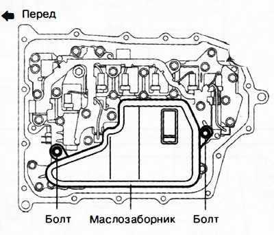
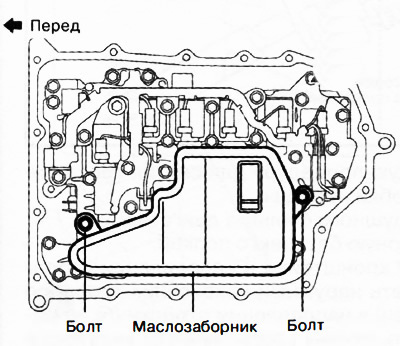
10. Remove the oil intake.
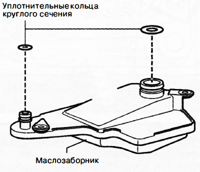
11. Remove the O-rings from the oil intake.
12. Remove the valve body.
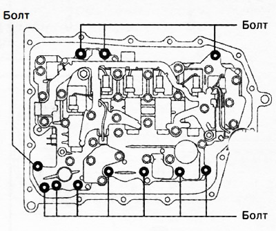
(Content based on information from Mazbook.ru)
Caution: Remove the valve body directly from below to avoid applying force to the valve body connector in a transverse direction.
13. Remove the valve body seal.
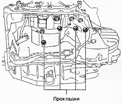
14. Remove the gaskets from the gearbox housing.
Installation
1. Install new gaskets into the gearbox housing.
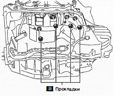
Note:replace the part with a new one after each removal.
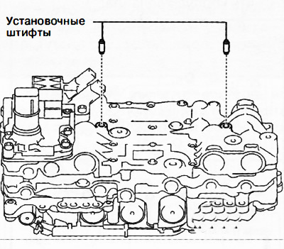
2. Insert the dowel pins into the valve body.
Note: If the dowel pin remains in the transmission housing, remove it and insert it into the valve body.
3. Gearboxes GW6A-EL, GW6AX-EL:
Prepare a plastic plate of the dimensions shown in the figure.
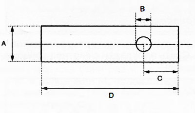
A: 20 mm. B: ∅ 8 mm. C: 15 mm. D: 65 mm.
Note: Use a plastic plate made of a material that is not too hard.
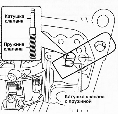
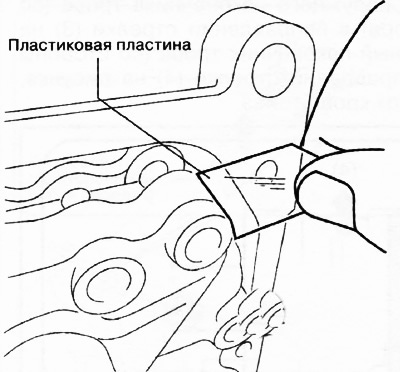
Insert the valve coil with the spring into the gearbox housing and fix the bypass valve with the spring using the plastic plate prepared earlier, as shown in the figure.
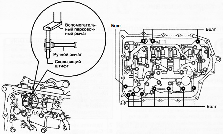
4. Install the valve body so that the auxiliary parking lever engages with the gap between the two surfaces of the spool part of the manual valve. Tighten the mounting bolts to a torque of 9-10 Nm.
Caution: Install the valve body so that the turbine/input shaft speed sensor, output shaft speed sensor and valve body connector do not contact the transmission case.
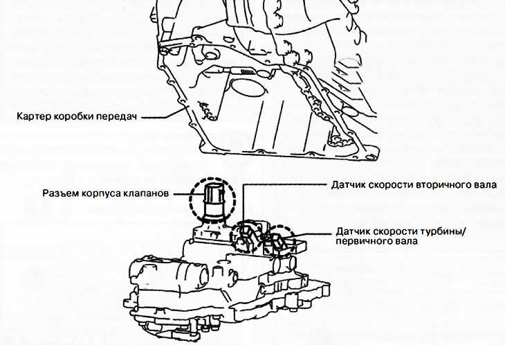
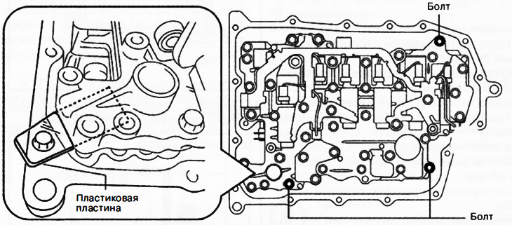
Gearboxes GW6A-EL, GW6AAX-EL
Caution: Since the valve body may be damaged by foreign materials, please remove the plastic plate carefully to prevent the valve body from getting into it.
5. Moving the hand valve in both directions (according to the arrow in the picture), make sure that the manual valve is properly connected to the auxiliary parking lever and the sliding pin of the mode sensor.
Note: If the hand valve moves only in the gap between the auxiliary parking lever and the surface of the hand valve, the hand valve and the auxiliary parking lever are connected correctly.
6. Install the oil intake sealing ring.
Note: If there is a large amount of sediment in the transmission oil pan, replace the oil pickup with a new one.
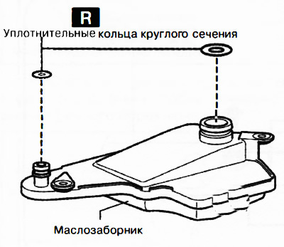
Note:replace the part with a new one after each removal.
7. Install the oil intake and tighten the mounting bolts to a torque of 9-10 Nm.
8. Apply a thin layer of silicone sealant (TB1217E) to the contact surfaces of the oil pan and gearbox housing.
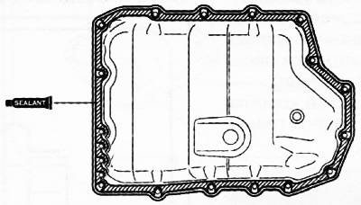
Caution: Remove any remaining silicone sealant from the mating surfaces of the gearbox housing and oil pan and degrease the sealing surfaces. Otherwise, leaks may occur.
9. Install the oil pan and tighten the new mounting bolts to 8-10 Nm before the sealant begins to harden.
10. Install front protective tray No.2.
11. Install the valve body seal.
12. Install the new hose clamp in the position shown in the figure.
Attention.
- Reusing a hose clamp may cause automatic transmission fluid leaks, so only a new clamp should be used.
- Set the hose clamp ears so that they are within the range A shown in the figure.
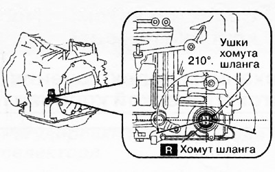
Note:replace the part with a new one after each removal.
Caution: Install the hose clamp so that it does not catch on the upper and lower edges of the seal to ensure proper sealing.
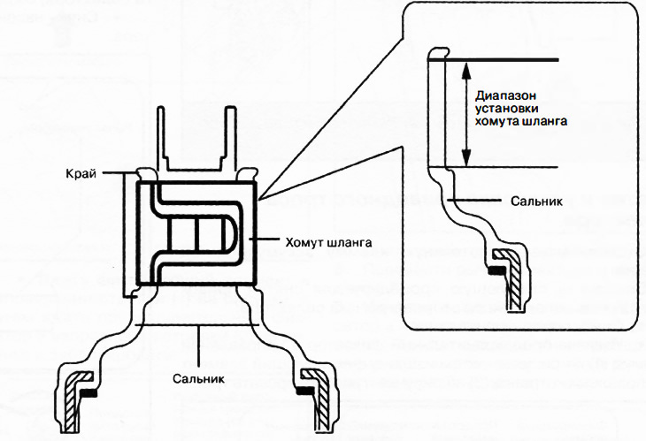
13. Connect the valve body connector.
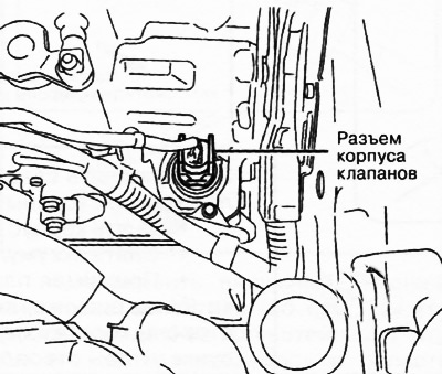
Attention.
- Be careful not to touch the connector terminals with your hands, as this may damage the terminals.
- Water or foreign objects entering the connector may cause poor connection and corrosion. When disconnecting the connector, be careful not to allow water or foreign objects to enter.
- Insert the connector without distorting it so as not to damage its terminals.
- Turn the connector lever until it clicks.
14. Fill the automatic transmission with working fluid.
15. Install the engine air filter assembly.
16. Connect the negative battery terminal.
17. If the valve body is replaced, perform the transmission control unit configuration and initial learning procedures (see the relevant section of this chapter).
18. Perform a check of the mechanical part of the gearbox (see the relevant section above in this chapter).
19. Perform a road test of the automatic transmission (see the relevant section above in this chapter).