


General description
1. The intake air temperature control system improves engine efficiency and reduces hydrocarbon emissions during warm-up by maintaining a controlled air temperature in the carburetor. This regulation of the incoming air temperature allows the carburetor to be slightly combined and the throttle valves to be calibrated.
2. The system uses a shock absorber assembly located in the air cleaner housing pipe, which controls the ratio of cold and warm air directed to the carburetor. This shock absorber is controlled by a vacuum diaphragm, which in turn is controlled by a temperature sensor in the air filter.
3. During the first kilometers of movement (depending on the outside temperature) this system has the greatest effect on engine management and emissions. When the engine is cold, the shock absorber flap closes off the air cleaner inlet tube, allowing only warm air from around the exhaust manifold to flow. Gradually, as the engine warms up, the flap opens the air duct, increasing the supply of cold air. Once the engine reaches normal temperature, the flap opens fully, allowing only cool fresh air to enter.
4. Because of this, it is important to check this system periodically to prevent the engine from running lean. If the air cleaner valve flaps are in the closed position at high temperatures, the engine will run poorly, lose speed and produce increased emissions until it warms up. A valve that sticks in position at high temperatures will cause the engine to run with a constant flow of hot air to the carburetor.
Examination
5. For service and inspection procedures for this system, contact Section 1. If you encounter problems with the system's operation while performing routine maintenance, please refer to the relevant Sections of this manual.
6. If the shock absorber inlet does not seal air from the manifold when the engine is cold, disconnect the vacuum hose at the diaphragm and place your thumb on the end of the hose to check for vacuum. If there is vacuum advancement to the diaphragm, check that the shock absorber inlet and connection are not frozen or clogged within the air filter duct. If a vacuum pump is available, disconnect the hose and point it at the engine to ensure the shock absorber valves are actuated. Replace the vacuum diaphragm if applying vacuum does not open the valve and route the hose correctly.
7. If there was no vacuum, check the hoses for cracks and ensure they are securely connected. If the hoses are intact and in good condition, replace the temperature sensor inside the air filter housing.
Replacement of parts
Air filter vacuum diaphragm
8. Disconnect the vacuum hose from the diaphragm.
9. Remove the mounting screw, disconnect the rod and rotate the diaphragm out of the air filter housing.
10. To install it, insert the diaphragm into the casing, rotate it into place, attach the rod and install the mounting screw.
11. Connect the vacuum hose.
Air filter temperature sensor
12. Remove the air filter to access its reverse side.
13. Mark the location and disconnect the vacuum hoses from the sensor.
14. Carefully note the position of the sensor, as it must be installed in exactly the same position. Remove the sensor from the air filter (photo).
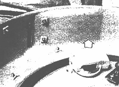
The temperature sensor vent can be removed (arrow) directly after disconnecting the vacuum hoses under the air cleaner assembly
15. Install the new sensor in the same position as the old one and connect the vacuum hoses.
(The original text can be found on: mazbook.ru)
16. Install the air cleaner element and the air cleaner top cover.