


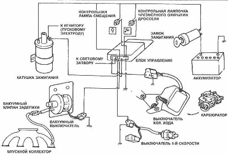
Details of the economy mode indication system
General description
1. Some models with manual transmission are equipped with an economy mode indicator system. Two lights on the instrument panel notify the driver to adjust the accelerator pedal pressure or to shift into a higher gear.
2. The lights do not come on in 5th (highest) gear and when braking. (On 1984 and later models, the throttle control light operates in all mechanisms.)
3. Besides the lights themselves, the main components of the system are the control unit located under the dashboard or behind the instrument cluster; vacuum switch connected to the intake manifold via a retard valve; 5th gear engagement mechanism and idle switch on the carburetor.
4. Control unit and cold switch. the course is divided by the coasting economy system (Chapter 4).
5. The control unit receives signals from the switches already mentioned, plus an input signal from the ignition coil. The signal from the ignition coil allows the unit to control the engine speed.
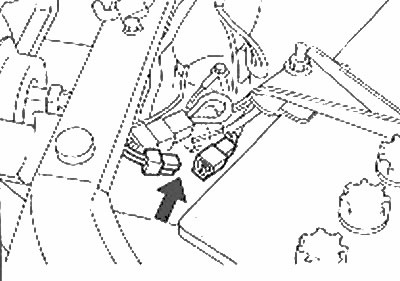
Switch connector (marked with arrows) 5th gear economy drive
(For details, see the website: MazBook.ru)
Examination
Displacement indicator
6. Start the engine and let it idle.
7. Gradually increase the engine speed and check the indicator lights at approximately 2800 rpm.
8. Disconnect the 5th gear shifter (closer to the battery) and repeat the check. The indicator should not light up accidentally. Reconnect the 5th gear switch connector.
Over-throttle indicator
9. For this test you will need a vacuum pump and a gauge.
10. Disconnect the vacuum hose from the switch and connect the vacuum pump and gauge in its place. Turn on the ignition. Have an assistant watch the indicator until vacuum is applied to the switch. The indicator should light when the vacuum is in the range of 0-120 mmHg and higher at higher values.
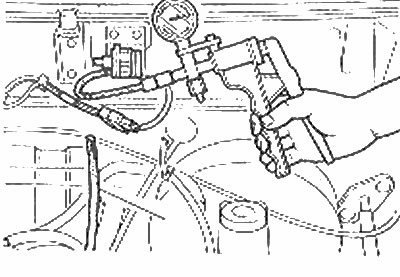
Provorna vacuum switch drive economy
11. On pre-1984 models, disconnect the 5th gear shifter and retest. The indicator should not light up accidentally. Reconnect the 5th gear switch connector and the vacuum hose with the switch.
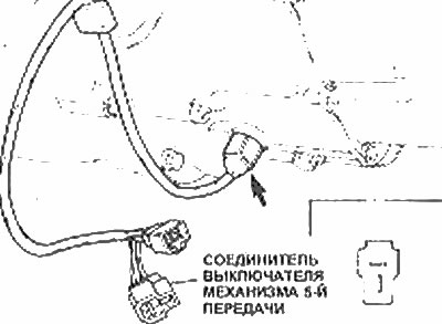
5th gear switch (marked with arrows) and electrical wiring
Replacement of parts
Control lights
12. Do as described in Section 12, Chapter 10.
Vacuum circuit breaker
13. Disconnect the vacuum hose and electrical connector from the switch. Disconnect the switch from the bulkhead.
14. Install the new switch and connect the hose and wiring.
Cold switch. move
15. Replacing the cold switch. the move is described in Chapter 4.
5th gear switch
16. Disconnect the 5th gear switch connector and follow the wiring back to the transmission.
17. Unscrew the switch from the transmission.
18. Install and connect the new switch, then check the transmission fluid level (Section 1, Chapter 4).
Control unit
19. No specific information regarding the location of the control unit was available at the time of writing this manual. It can be accessed by removing the lower trim of the instrument panel, dash panel or instrument cluster.