


Contents: Motor oil ⇓ Coolant ⇓ Windshield washer fluid ⇓ Rear window washer ⇓ Headlight washer ⇓ Battery electrolyte ⇓ Brake fluid ⇓ Manual transmission oil ⇓ Automatic transmission fluid ⇓ Power steering fluid ⇓
1. A number of fluids are used in various vehicle systems. These fluids must be topped up periodically, otherwise components that depend on their level will be damaged. Cm. "Recommended lubricants and fluids" at the beginning of this guide to choose the correct type and brand of liquid. Before checking the level of any fluid, park the car on a level, horizontal surface.
Motor oil
2. The engine oil level is measured using a dipstick. The dipstick is lowered through the tube into the sump, to the base of the engine.
3. The oil level should be checked at least 15 minutes after the engine has been turned off. If the level is measured immediately after driving the vehicle, some oil will remain in the upper engine components and the measurement will be inaccurate.
4. Remove the dipstick from the tube (photo) and wipe off all the oil from its end. Reinsert the dipstick into the pan and remove it again. The level should be between the L and F marks (photo).
5. To raise the level from the L mark to the F mark on the dipstick, 1 liter of oil is required. Do not allow the level to drop below the L mark, as this may cause engine damage. On the other hand, do not overfill the pan by raising the level above the F mark, as this may result in oil contamination of the spark plugs, oil leaks or damage to the seals.
6. To add oil, remove the plug located on the valve cover. Use a funnel.
7. If the oil level drops too quickly, this indicates an oil leak or internal wear on the engine. If there are drops of water in the oil or it becomes cloudy, components have failed and the engine should be diagnosed immediately. Also check the condition of the oil - smear the oil up the dipstick with your thumb and forefinger, checking for small grains of sand and metal particles. If such inclusions are present, change the oil (Chapter 16).
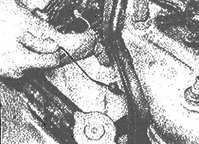
The engine oil dipstick is located on the front of the engine (radiator side) |
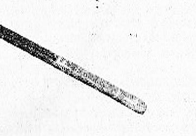
The oil level should be between the F and L marks |
Coolant
8. All vehicles described in this manual are equipped with a sealed cooling system. The white coolant expansion tank, attached to the inner fender panel, is connected by a hose to the radiator cap. Expanding when heated, the coolant leaves the radiator and enters the expansion tank. When the engine cools down, the coolant automatically returns to the radiator, thus maintaining the correct fluid level at all times.
9. The coolant level should be checked when the engine is hot. The fluid level in the expansion tank should be near the "Full" mark on the tank wall (photo). If the system has completely cooled down, also check the radiator level by removing the radiator cap.
10. Warning: Never remove the radiator cap or expansion tank cap while the engine is still hot - hot steam and splashes can cause serious burns. To check the radiator level, wait for the system to cool, then wrap a thick cloth around the radiator cap and turn it to the first stop. If steam starts escaping from under the lid, wait until the system has cooled completely, then remove the lid. The expansion tank cap can be carefully removed after the water has stopped boiling.
11. If you need to add a small amount of coolant, you can use ordinary water. If the fluid level in the system is quite low, mix antifreeze with water in the required proportions (indicated on the container) and add the mixture to the system. Avoid contact of antifreeze with your skin or painted surfaces of your vehicle. Rinse off any spilled drops immediately with plenty of water.
12. Bring the coolant level in the expansion tank to the "Full" mark. If the radiator cap was removed, add coolant until the radiator is full, then replace the cap.
13. Also check the condition of the coolant. It should be relatively light. If it is brown or rust colored, the liquid must be drained, the system flushed and refilled (Chapter 26).
14. If the cooling system needs to be topped up frequently, check the radiator cap. Also inspect the system for leaks from cracked hoses, loose hose connections, damaged gaskets, etc.
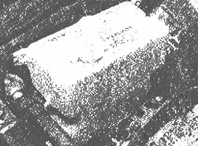
The coolant and windshield washer reservoirs are located next to each other, but are filled with different fluids, so don't confuse them.
Windshield washer fluid
15. The windshield washer fluid is located in a plastic reservoir located next to the coolant reservoir. The tank should be filled no more than 2/3 to allow for expansion when it freezes. Using additives such as a special flushing fluid will help lower the freezing point of the liquid. Do not use antifreeze as it will damage the paint.
16. To prevent icing, in cold weather, warm up the windshield with the defroster before turning on the washer.
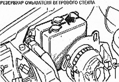
Windshield washer reservoir
Rear window washer
17. On models equipped with rear window washers, the reservoir is mounted behind the panel in the rear of the cabin. The level in it should also be maintained within 2/3 of filling.
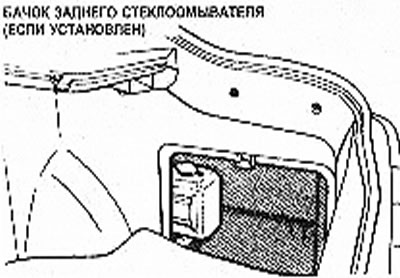
Rear window washer reservoir (if installed)
Headlight washer
18. Some models are equipped with headlight washers, the reservoir for which is located in the engine compartment. Due to the different placement of components in the engine compartment, it is difficult to indicate the location of the reservoir. Follow the washer pipes and locate the reservoir. The reservoir should be filled no more than 2/3 with the same fluid used in windshield washers.
Battery electrolyte
19. Some of the models described are equipped with maintenance-free batteries that do not have a filler cap. These batteries do not require adding water (photo).
This type of battery does not require topping up with water, however, normal maintenance should be performed
20. If the model is equipped with a refillable battery, periodically remove the battery compartment covers to ensure the plates are covered with a 10-20 mm thick layer of electrolyte. Top up the battery with distilled water if necessary. Do not overfill the battery and wipe up any spilled water immediately. Install the compartment covers (photo).
Add distilled water to the battery |
Install the cell cover |
Brake fluid
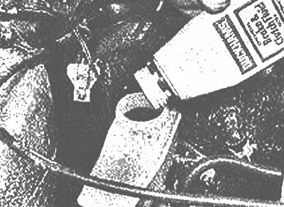
21. The master brake cylinder is installed in the engine compartment, on the front part of the brake booster unit. The fluid level should be maintained near the "Max" mark on the cylinder reservoir (photo).
Add brake fluid
22. If it is necessary to add brake fluid, before removing the reservoir cap, thoroughly wipe its outer surface with a clean rag to prevent dirt from entering the brake system.
23. When adding liquid, pour it into the tank carefully, trying not to spill it on surrounding painted surfaces. Only add fluid specified in the Specifications; mixing different types of brake fluid in the system may cause damage. Cm. "Recommended lubricants and fluids" or the operating instructions for your vehicle.
24. Also inspect the fluid and cylinder for contamination. The manufacturer recommends replacing the fluid by bleeding it at specific intervals (Section 9). The fluid should also be replaced if suspended particles, sediment, or water droplets are detected.
25. After filling the tank to the proper level, install the cap correctly to prevent liquid leakage.
26. The brake fluid level in the master cylinder gradually decreases as the brake pads wear out. If you have to add fluid to the master cylinder frequently, there is a leak in the brake system that should be fixed immediately. Check all brake lines and connections, as well as wheel cylinders and brake booster unit (see Chapter 13).
27. If, when checking the fluid level in the master cylinder, you find that one or both reservoirs are empty or almost empty, bleed the brake system (Section 9).
Manual transmission oil
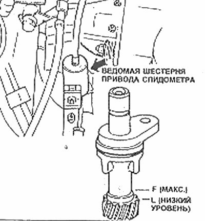
28. Manual transmissions do not have a dipstick. The oil level can be checked by removing the speedometer drive mechanism.
29. Remove the mounting bolt, take out the mechanism, wipe the driven gear and reinsert the drive. Remove the mechanism again and make sure the oil level is between the F and L marks as shown in the illustration.
30. If the transmission needs more oil, add it through the speedometer drive installation hole using a syringe.
31. Install the speedometer drive, screw in the mounting bolt and tighten it securely. Take a short drive and check the speedometer drive hole for leaks.
Automatic transmission fluid
32. The automatic transmission fluid level must be maintained carefully. Low fluid levels can cause slippage or loss of drive, while overfilling can cause foaming and fluid loss.
33. Park the car on a level, horizontal surface. Apply the parking brake, start the engine at idle, and move the transmission mode selector through each position, ending with the "Park" position. Check the fluid level.
Note: If the vehicle has just been driven at high speed for a long distance, driven on city streets in hot weather, or towing a trailer, the level reading will be inaccurate. In these cases, wait until the liquid cools down (approximately 30 minutes).
34. After warming up the transmission to normal operating temperature, remove the level measuring harness from the filler tube (photo).
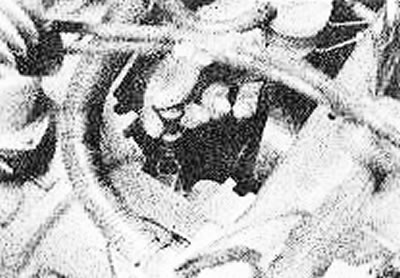
The automatic transmission fluid level dipstick is located at the rear of the transmission
35. Wipe the dipstick dry with a clean cloth and reinsert it into the tube.
36. Remove the dipstick again and check the fluid level.
37. The level should be between marks L and F (photo).
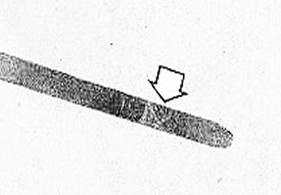
The automatic transmission fluid level should be maintained within the shaded area on the dipstick (arrow) - do not overfill the transmission
38. Add the recommended type of fluid to fill the transmission to the proper level. It takes approximately 600 ml of liquid to raise the level from the L mark to the F mark (with a hot transmission). Add liquid little by little and monitor its level. Use extreme caution to prevent dirt or foreign particles from entering the transmission.
39. Also check the condition of the fluid. If the fluid at the end of the dipstick is dark, reddish-brown, or has a burnt odor, replace the fluid. If you have any doubts about the condition of the fluid, buy some fresh fluid and compare their color and smell.
Power steering fluid
40. Unlike non-power steering, a power steering system runs on fluid and may require refilling over time.
41. The power steering pump feed tank is located behind the radiator near the front of the engine (photo).
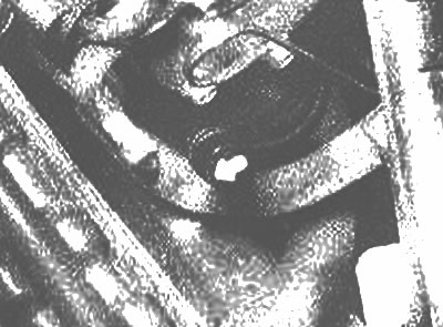
The power steering reservoir is located near the engine oil dipstick
42. To check, the front wheels must be pointed straight ahead and the engine must be turned off.
43. Use a clean cloth to clean the tank lid and the area around the lid. This will help prevent foreign particles from entering the tank during inspection.
44. Start the engine and allow it to warm up to normal operating temperature.
45. Remove the dipstick, wipe it with a clean cloth and reinsert the dipstick. Remove the dipstick again and check the fluid level. The level should be between the "Add" and "Full Hot" marks.
46. If fluid needs to be added, use only the specified fluid type. Pour it directly into the reservoir using a funnel.
47. Install the dipstick so that the arrow on its cover points forward, toward the radiator.
48. If the reservoir must be refilled frequently, carefully check all power steering hoses, their connections, the power steering pump, and the steering rack and pinion assembly for leaks.