MazBook.ru
English Русский
Български
Беларускі
Український
Српски
Hrvatski
Română
Polski
Slovenský
Magyar
• Bookmark • Sitemap • Contacts •   
Cars Opel Cars Ford Cars Volkswagen Cars Audi Cars Kia Cars Renault Cars Peugeot


Familia Capella Mazda3 Mazda6 CX-? Others Articles
Capella 3 (1982-1992, petrol) Capella 3 and 4 (1982-1992) Capella 4 (1987-1992) Capella 5 (1991-1997) Capella 6 (1997-2005, petrol)

Clutch — removal, inspection and installation (Mazda Capella GC)

  • Home
  • Mazda Capella
  • Capella GC (1982-1992)
  • Transmission
  • Clutch and drive shafts
  • Clutch — removal, inspection and installation
0
Contents: Removal ⇓ Inspection ⇓ Installation ⇓
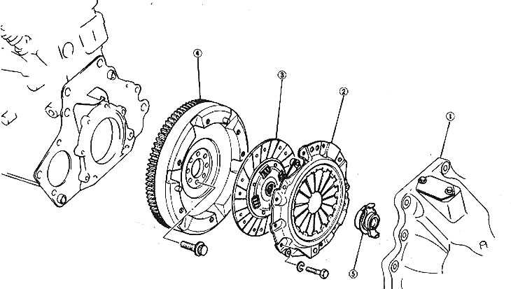
Clutch component locations

Clutch component locations

1. Transmission; 2. Clutch housing; 3. Fiction disc; 4. Flywheel; 5. Release bearing


Removal


1. Remove the transmission (Section 7).

2. Apply alignment marks to the pressure plate and flywheel so that they can be installed in the same position later.

3. When removing the pressure plate, hold the friction disc with a special tool or a screwdriver handle.

4. Lock the flywheel ring gear and evenly loosen the pressure plate mounting bolts, turning them one turn in a diagonal sequence to prevent the cover from deforming.

5. Remove the pressure and friction discs.

6. Carefully, without touching the surface of the linings, separate the friction disc.

7. Remove the return spring from the clutch release fork hook, turn the release lever and remove the release bearing.
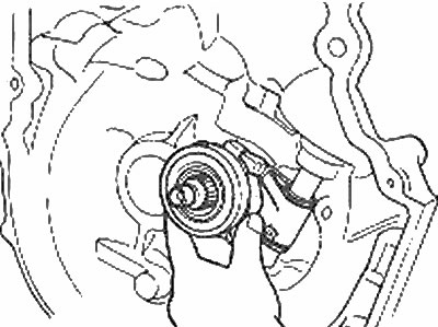
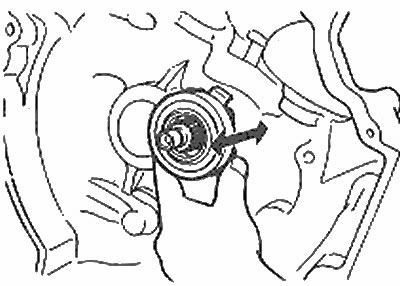
Remove the release bearing

Remove the release bearing


8. Remove the clutch release fork bolt and remove the fork assembly with the lever.

Inspection


9. Remove dust from the clutch housing using an electric vacuum cleaner or a clean cloth. Do not use compressed air for this, as you may inhale dust, which is hazardous to your health as the dust contains asbestos.

10. Inspect the pressure plate for damage and wear of the diaphragm spring, scratches and discoloration (indicates overheating) rubbing surface, as well as damage and deformation of the cover. Replace the pressure plate with a new unit if there is any doubt about its condition.

11. Inspect the flywheel surface for signs of uneven wear, which indicates improper installation or damage to the friction disc springs. Check for burns, grooves, cracks and other damage. A flywheel with a large number of nicks and grooves must be re-ground on a machine. Shallow scratches can be removed from the flywheel surface using fine-grain sandpaper.

12. Inspect the clutch friction linings for signs of contamination with oil, grease, etc. and replace the disc with a new one if such contamination is detected. Check the linings for wear by measuring the distance between the rivet head and the lining surface. Replace the disc with a new one if the pads are worn as shown in the figure.
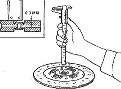
Measure the wear of the friction linings

Measure the wear of the friction linings


13. Inspect the disc for deformation, wear, broken rivets, weak springs and damaged grooves. Pull the disc onto the input shaft to ensure it is seated correctly and the grooves are not damaged or worn. Replace the disk with a new one if there is any doubt about its condition.

14. Check the release bearing for wear and deformation and make sure it rotates smoothly and moves easily toward the input shaft. It is recommended to replace the bearing every time the clutch is removed, unless the vehicle has traveled very little mileage since the last bearing replacement.
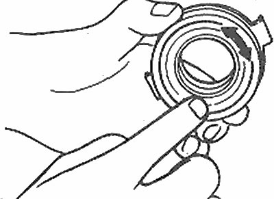
Make sure the bearing rotates smoothly and easily using a bearing puller

Make sure the bearing rotates smoothly and easily using a bearing puller
The release bearing must move smoothly in the grooves

The release bearing must move smoothly in the grooves

15. Inspect the surface of the clutch housing, release lever and return spring for wear, cracks, deformation, etc. damage, replace if necessary.


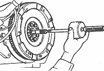
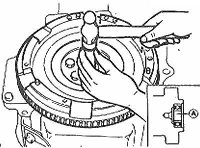
16. Make sure that the clutch support bearing in the crankshaft rotates easily and smoothly (rotate it with your finger). Replace the bearing if necessary by removing it with a sliding hammer and installing a new one into the crankshaft recess using a socket or piece of tubing and a hammer. Lubricate the new bearing and install it as shown in the figure.
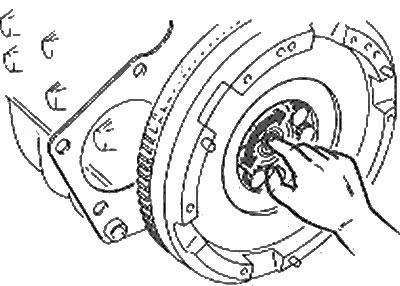
Check the rotation of the support bearing

Check the rotation of the support bearing
Remove the thrust bearing using a sliding hammer

Remove the thrust bearing using a sliding hammer

Install the support bearing assembly into the crankshaft recess

Install the support bearing assembly into the crankshaft recess

A = 2.45±0.3 mm


Installation


17. Before installation, apply a small amount of molybdenum grease to the release bearing and input shaft/friction disc grooves. Make sure that the lubricant does not come into contact with the rubbing surfaces of the friction disc, flywheel and pressure plate.

18. Install the friction disc onto the flywheel. Hold the friction disc with a special tool or a suitable round bar and install the pressure plate, aligning the alignment marks.
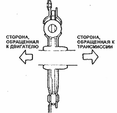
Friction disc in section - showing the correct orientation of the disc

Friction disc in section - showing the correct orientation of the disc


19. Install the pressure plate bolts and tighten them in a diagonal pattern so that the pressure plate is flush with the friction disc. Center the disc relative to the clutch support bearing (at the end of the crankshaft), using a special alignment tool or a suitable round rod (photo).
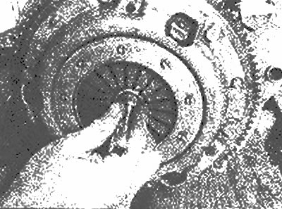
The socket can be used as a clutch centering tool

The socket can be used as a clutch centering tool


Note: If the disc is not centered, the transmission will not install.


20. Tighten the pressure plate bolts by turning them half a turn in a diagonal sequence, using the tightening torque specified in the Specifications. Do not remove the alignment tool while tightening the bolts.

21. Install the release lever, fork, spring and bearing.

22. Remove the alignment tool and install the transmission.
This article is available at: russian, bulgarian, belarusian, ukrainian, serbian, croatian, romanian, polish, slovak, hungarian
This text was checked by: Evdokia Filimonova
Share with friends on social networks:

Previous
Capella 3 » Clutch and drive shafts
Next

Clutch cable — removal and installation
Clutch pedal — removal and installation
Clutch — checking operation
Clutch — general description
Clutch and Drive Shaft Specifications
Drive shaft — general description
Drive shaft and connecting shaft — removal and installation
Drive shaft boot — replacement
More articles on repairing other Mazda models
Detailed technical specifications of the clutch Mazda Familia 5 (1985-1989)
General information about the clutch Mazda3 BK (2003-2009)
General information about the clutch Mazda6 GG (2002-2008)
Clutch Pedal Position Sensor Mazda CX-5KE (2012-2017)
Clutch — design description Mazda 121 (3) (1996-2003)
Link in different formats to this article
Comments and feedback from visitors
No comments yet


How much will 12 + 41 ?


Capella 6 (1997-2005, petrol) 
  • General information
  • Introduction to guide
  • User manual
  • Troubleshooting
  • Maintenance
  • Power unit
  • 4-cylinder engines
  • 6-cylinder engines
  • Engine overhaul
  • Cooling and ventilation
  • Power and exhaust systems
  • Engine electrics
  • Control system
  • Transmission
  • Mechanical gearbox
  • Automatic gearbox
  • Clutch and drive shafts
  • Chassis
  • Brake system
  • Car suspension
  • Steering
  • Body
  • Exterior (external elements)
  • Interior (internal elements)
  • Doors, windows and locks
  • Electrical equipment
  • Equipment and devices
  • Electrical circuits
Capella 5 (1991-1997) 
  • General information
  • User manual
  • Maintenance
  • Helpful hints
  • Power unit
  • Petrol engines 1.6 and 1.8
  • Petrol engines 2.0
  • 2.5 petrol engines
  • Overhaul engines 1.6 and 1.8
  • Overhaul engines 2.0 and 2.5
  • Diesel engine 2.0
  • Engine electrics
  • Cooling system
  • Air conditioner
  • Carburetor Nikki 30/34
  • Power system (1.6 and 1.8)
  • Power system (2.0 and 2.5)
  • Control system
  • Transmission
  • Mechanical gearbox
  • Automatic gearbox
  • Clutch and axles
  • Chassis
  • Brake system
  • Suspension and wheels
  • Steering
  • Body
  • Exterior (external elements)
  • Interior (internal elements)
  • Doors and windows
  • Electrical equipment
  • Equipment and devices
  • Electrical circuits
Capella 4 (1987-1992) 
  • General information
  • Introduction to manual
  • Vehicle specifications
  • Power unit
  • Engine repair
  • Lubrication system
  • Cooling system
  • Fuel system (carburetor)
  • Fuel injection (FE)
  • Fuel injection (DOHC)
  • Fuel system (diesel)
  • Ignition system
  • Transmission
  • Clutch
  • Gearbox
  • Drive shafts
  • Chassis
  • Front suspension
  • Rear suspension
  • Steering system
  • Brake system
  • Electrical equipment
  • Equipment and devices
  • Electrical circuits
Capella 3 and 4 (1982-1992) 
  • General information
  • User manual
  • Maintenance
  • Power unit
  • Gasoline engine
  • Engine overhaul (gasoline)
  • Diesel engine
  • Cooling and heating
  • Supply system
  • Ignition system
  • Emission reduction
  • Transmission
  • Clutch
  • Mechanical gearbox
  • Automatic gearbox
  • Drive shafts
  • Chassis
  • Brake system
  • Suspension and wheels
  • Steering
  • Body
  • Exterior (external elements)
  • Interior (internal elements)
  • Electrical equipment
  • Equipment and devices
  • Power devices
  • Electrical circuits
Capella 3 (1982-1992, petrol) 
  • General information
  • User manual
  • Maintenance
  • Troubleshooting
  • Late models
  • Power unit
  • Engine in car
  • Engine overhaul
  • Cooling and heating system
  • Fuel and exhaust system
  • Engine electrical system
  • Emission control system
  • Transmission
  • Mechanical gearbox
  • Automatic gearbox
  • Clutch and drive shafts
  • Chassis
  • Brake system
  • Suspension and wheels
  • Steering
  • Body
  • Exterior (external elements)
  • Interior (internal elements)
  • Electrical equipment
  • Equipment and devices
  • Lighting and lamps
  • Electrical circuits
MazBook.ru © 2018–2026 · Mobile version · Articles and news · Sitemap: EN BG BY UA RS HR RO PL SK HU · Feedback · Site search · Add to bookmarks Familia 5 (BF) · Familia 6 (BG) · Capella 3 (GC) · Capella 3 and 4 (GC) · Capella 4 (GD) · Capella 5 (GE) · Capella 6 (GF) · Mazda3 BK · Mazda6 GG · CX-5KE · Mazda 121 (3) · Mazda BT-50 (1) ·
By continuing to use the site, you agree to the use of cookies 🔐