


Contents: Motor oil ⇓ Coolant ⇓ Windshield and headlight washer fluid ⇓ Electrolyte in a battery ⇓ Brake fluid ⇓ Manual transmission oil ⇓ Automatic transmission fluid ⇓ Power steering system fluid ⇓
Caution! Check the operating fluid level with the vehicle on a level, horizontal surface.
Motor oil
Motor oil is of great importance for the normal and long-lasting operation of the engine. It must retain its properties even under extreme conditions and age as slowly as possible. Motor oil reduces friction between sliding surfaces, which reduces wear on pistons with piston rings, cylinders, bearings and valve train components.
Motor oil is also used for micro-sealing between pistons, piston rings and cylinder walls, as there is always a gap of several microns between these parts. Thanks to the additional sealing effect of the oil, the high gas pressure resulting from combustion is transferred without loss to the piston crown and converted into kinetic energy. This ensures optimum engine power.
The engine oil level is checked using the engine oil level indicator (dipstick), located on the front side of the engine near the radiator. The oil level indicator (dipstick) is inserted through the guide pipe into the oil pan located at the bottom of the engine.
It is recommended to check the oil level before driving the car or 15 minutes after starting the engine. If you check the oil level immediately after starting the vehicle, some oil will remain in the upper part of the engine, resulting in incorrect readings.
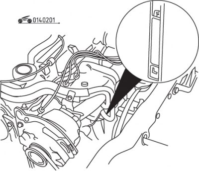
Figure 2.1. Location of the "L" and "F" marks on the oil level gauge
Remove the dipstick from the pipe and wipe it with a clean rag or paper towel. Insert the clean pointer through the guide tube into the oil pan as far as it will go, wait a moment and then remove it again. The oil level should be between the "L" and "F" marks on the gauge (figure 2.1).
The volume of engine oil between the "L" and "F" marks on the gauge is 1 liter. The oil level should not fall below the lower mark. A decrease in the level by more than 0.25 l does not pose a danger to the engine. If more oil is needed and the vehicle is driven at high engine speeds, the oil pressure may drop to a dangerous level, which the driver will be informed of by the oil pressure warning light located in the instrument cluster.
It is not recommended to fill the oil above the "F" mark on the gauge, as a large amount of it enters the combustion chamber through the crankcase ventilation system and burns in it.
Oil is added to the engine after removing the oil filler cap. To reduce the amount of spilled oil, use a funnel.
Checking your oil level is an important part of your vehicle's preventative maintenance. If you notice a significant decrease in the oil level over a relatively short period of time, this indicates the presence of oil leaks or worn engine parts, which must be addressed immediately. If drops of water get into the oil or it has a pale milky tint, it means that coolant has entered the lubrication system. In this case, it is necessary to immediately check and repair the engine. At the same time as checking the oil level, you should check the condition of the coolant in the expansion tank. After removing the oil level gauge from the engine, wipe the oil off the gauge with your thumb and forefinger to check for any dirt or metal particles that may stick to it when you measure the level. Contamination and metal particles in engine oil indicate the need for replacement.
Coolant
All vehicles are equipped with a cooling system with forced circulation of liquid under pressure. The hose from the expansion tank, secured to the inner wing panel, is connected to the radiator cap. When the engine heats up during operation, coolant from the radiator flows through the connecting hose into the expansion tank. When the engine cools down, the coolant automatically returns to the radiator, maintaining the coolant level.
The coolant level must be checked on a hot engine: in the expansion tank, it should be near the "full" mark on the side of the tank. If the engine is cold, remove the cap and check the coolant level in the radiator.
Caution! Use caution when opening the expansion tank cap on a hot engine, as escaping vapors can cause severe burns. To do this, cover the expansion tank cap with a thick layer of cloth and slowly unscrew the cap until a hissing sound is heard. After the hissing stops, slowly unscrew and remove the cap from the expansion tank.
If you only need to add a small amount of coolant, you can use regular water. When adding large amounts of liquid, it is necessary to maintain the recommended concentration of ethylene glycol in the water. Avoid contact of coolant with clothing or vehicle paintwork. Otherwise, rinse the surface with plenty of water.
The expansion tank should be filled with coolant to the "full" mark. If the radiator cap is removed, add coolant until the radiator is full, then replace the cap.
When checking the coolant level, pay attention to its condition. The liquid should be relatively clear. If it is brown or rust colored, drain it, flush the system and fill with fresh coolant.
If the cooling system requires periodic top-up to maintain the proper level, check the radiator cap seal. Check for leaks in the system caused by damaged hoses and gaskets, loose hose connections, etc.
Windshield and headlight washer fluid
Windshield washer fluid
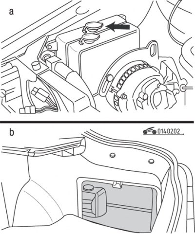
Figure 2.2. Location of the windshield (a) and rear window (b) washer reservoir
The fluid is located in a plastic tank located next to the expansion tank (figure 2.2). The tank should be filled no more than 2/3 of its volume, taking into account the possible expansion of the liquid when freezing. In cold weather, use special antifreeze liquids, which can be purchased at the store. It is strictly forbidden to use antifreeze as an additive, as this will damage the paintwork of the car.
Before using the washer fluid, warm the windshield with a defroster to prevent icing in cold weather.
Rear window washer fluid
On models equipped with a rear window washer, the reservoir is located behind the panel in the luggage compartment and should also be filled to 2/3 capacity using the same fluid as the windshield washer.
Headlight washer fluid
Some models are equipped with a headlight washer, the reservoir of which is located in the engine compartment. Due to the variety of reservoir configurations used, trace the tubing from the washer to the reservoir to determine its location. The reservoir should also be filled to 2/3 of its capacity using the same fluid as the windshield washer fluid.
Electrolyte in a battery
Under normal vehicle operating conditions, the battery requires virtually no maintenance. At high ambient temperatures, it is recommended to check the electrolyte level in the battery from time to time. The electrolyte level should also be checked when charging the battery. It should always be between the "MIN" and "MAX" marks located on the longitudinal sides of the battery.
Caution! The electrolyte is very aggressive. When working with batteries, you must wear gloves and safety glasses. Avoid allowing acid droplets and particles containing lead compounds to come into contact with eyes, skin or clothing.
Caution! Do not tilt the battery, as electrolyte may leak from the ventilation openings. If electrolyte gets into your eyes, rinse them immediately with clean water for several minutes. After this, consult a doctor. If electrolyte comes into contact with skin or clothing, immediately neutralize the acid with alkaline soap and wash the affected area with plenty of clean water.
If the electrolyte level drops, add distilled water to the appropriate jars up to the "MAX" mark. This should be done before the electrolyte level drops below the "MIN" mark.
Do not fill the electrolyte above the required level, as it will leak out through the ventilation holes, which may cause damage to the paintwork and corrosion of the body.
After adding electrolyte, the corresponding battery jars should be tightly closed with plugs.
Brake fluid
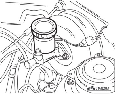
Figure 2.3. Location of the brake fluid reservoir on the master cylinder
The brake master cylinder is installed in the engine compartment. The brake fluid level should be maintained near the "MAX" mark on the reservoir (figure 2.3).
If the brake fluid level is low, wipe the top of the reservoir and the cap with a clean rag before removing the cap to prevent contamination of the brake system.
When adding brake fluid, care must be taken to fill the reservoir thoroughly and not spill brake fluid on surrounding painted surfaces. Make sure you use the recommended fluid, as mixing different types of brake fluid can cause damage to the brake system.
The manufacturer recommends replacing the brake fluid by bleeding the brake hydraulic system. Brake fluid must be replaced if dirt particles or water droplets are found in it.
After filling the reservoir to the appropriate level, it is necessary to ensure that the cap is installed correctly to prevent leakage of brake fluid and/or reduction of pressure in the system.
The brake fluid level in the master cylinder will drop slightly as the brake pads or discs wear during normal operation. If you need to constantly top up the fluid to maintain the required level, this means there are leaks in the brake system that need to be fixed immediately.
If, when checking the brake fluid level, you find that one or both sections of the reservoir are almost empty, you must bleed the brake system after adding brake fluid.
Manual transmission oil
There is no provision for using a level gauge to determine the oil level in manual transmissions. The fluid level is checked by removing the speedometer drive gear.
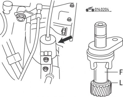
Figure 2.4. Location of the "F" and "L" marks on the speedometer drive gear for checking the oil level in a manual transmission
Remove the bolt, remove the speedometer drive gear, wipe, clean and reinstall it. Remove the gear again and check the oil level, which should be between the "F" and "L" marks as shown in the figure 2.4.
To top up the oil in the manual transmission, use a syringe through the hole for the speedometer drive gear. Install the speedometer drive gear and secure it with the bolt. After driving the vehicle for a short time, check for any oil leaks from the gearbox.
Automatic transmission fluid
The automatic transmission is filled with a working fluid, which serves to lubricate and regulate the hydraulic pressure in the gearbox.
The level of working fluid in an automatic transmission must be maintained within strictly defined limits. Low fluid levels can cause clutch slippage or reduced traction, while high levels can cause foaming and transmission hydraulic system malfunction. If the fluid level is low, do not add fluid immediately; first check the gearbox for leaks. Sealing work on the box should be carried out at a service station.
Apply the parking brake, start the engine, move the selector lever through all positions, and leave it in the "Park" position. The fluid level should be checked with the vehicle raised and the engine idling.
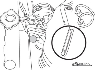
Figure 2.5. Location of the transmission fluid level indicator in an automatic transmission
At normal operating temperature, remove the dipstick from the filler tube located at the rear of the transmission case to measure the transmission fluid level (figure 2.5).
Caution! The automatic transmission fluid level will be incorrectly determined immediately after extended driving at high speeds, towing a trailer, in warm weather, or while driving in the city. In these cases, it is necessary to wait until the working fluid has cooled for 30 minutes.
Wipe the level indicator with a clean cloth and insert it back into the filler tube until the cap fits tightly.
Remove the indicator and determine the level of the working fluid, which should be between the "L" and "F" marks (see figure 2.5).
Add the recommended type of transmission fluid to fill the transmission to the required level.
The volume of working fluid between the "L" and "F" marks on the indicator on a hot gearbox is 1 liter, so you should add fluid little by little, constantly checking the level. Work very carefully to prevent dirt or foreign objects from getting into the gearbox.
At the same time as determining the fluid level, check its condition. If the fluid on the level indicator is dark red-brown in color or has a burnt smell, then this fluid must be replaced. If you have any doubts about the condition of a liquid, purchase a new sample liquid and compare both liquids for color and odor.
Power steering system fluid
The power steering system is powered by a pump that supplies fluid under pressure into the corresponding cavity of the steering gear, significantly reducing the effort required to turn the steering wheel to turn the front wheels of the vehicle.
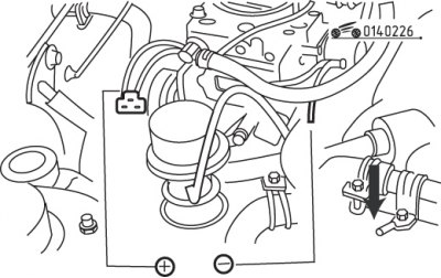
Figure 2.6. Location of the power steering fluid reservoir
The power steering fluid reservoir is located behind the radiator at the front of the vehicle (figure 2.6).
When checking the fluid level, the front wheels should be positioned straight ahead and the engine stopped.
Wipe the tank lid and the area around it with a clean cloth. This will prevent any objects from getting into the reservoir when checking the fluid level.
Start and warm up the engine to normal operating temperature.
Remove the level indicator and wipe it with a clean cloth. Reinsert the pointer into the reservoir, then remove it and determine the fluid level, which should be between the "L" and "F" marks.
If fluid needs to be added, add the required amount of the recommended fluid through the funnel directly into the reservoir.
The level gauge must be reinstalled so that the arrow on the cap points forward towards the radiator.
If frequent fluid top-up is required, check all power steering hoses, hose connections, power steering pump and gears for leaks.