


Removal
Remove the hood.
Remove the battery, engine mounts and drain the coolant.
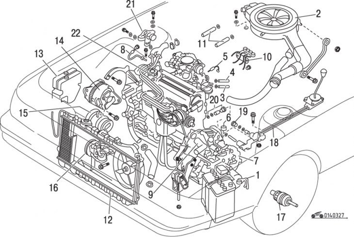
Figure 3.27. Sequence of removal of components and assemblies when removing the engine from the vehicle: 1 – negative battery terminal wire; 2 – air filter; 3 – fuel line; 4 – return fuel line; 5 – throttle cable; 6 – speedometer drive cable; 7 – clutch drive cable; 8-motor connection wire with "ground"; 9 – brake booster hose; 10 – three-way power steering valve and bracket; 11 – heater hoses; 12 – fan and radiator; 13 – expansion tank and washer reservoir; 14 – generator; 15 – air conditioning compressor; 16 – power steering pump; 17 – drive shafts; 18 – gear shift rod (manual transmission); 19 – extension rod (manual transmission); 20 – flexible connections of the exhaust system, bolts and nuts for fastening; 21 – torsion bar engine mount limiter; 22 – power unit assembly
Remove the air filter (figure 3.27).
Disconnect the fuel supply and outlet pipes from the fuel pump.
Disconnect the air and throttle actuators.
Disconnect the speedometer drive cable.
Disconnect the clutch cable (manual transmission) or control cable (automatic transmission).
Disconnect the ground wire from the vehicle's gearbox.
Disconnect the brake booster hose.
Remove the plugs from the vacuum switches and remove the bracket.
Disconnect the hoses from the heater.
Remove the plugs from the traction relay and vacuum sensor (if any) and turn them out of the firewall.
Disconnect the wiring connectors from the engine.
Disconnect all other electrical connectors in the engine compartment.
Disconnect the wire from the ignition coil.
Disconnect the evaporator hoses from the tank (if they are provided for by the design).
Disconnect the radiator hoses, disconnect the connector from the radiator fan motor.
Remove the radiator.
Remove the expansion tank and washer reservoir.
Remove the generator and air conditioning compressor from the bracket (if provided for by design). Move the compressor to the side, being careful not to damage the hoses (are under high pressure), and secure it with a piece of wire.
Raise the front of the car and place it on stands, remove the front wheels and mud flaps.
Remove the power steering pump (if provided for by design) together with the hoses, move it to the side and secure it with a piece of wire.
Drain the oil from the gearbox.
Disconnect the front stabilizer bar link and push or pull the drive shafts out of the transmission. To fix the position of the differential gears, insert special plugs or internal constant velocity joints of the drive shafts into the gearbox instead of the drive shafts.
On manual transmission models, disconnect the shift linkage and link extension from the transmission.
Disconnect the exhaust pipe from the muffler.
Remove the rubber plug and mudguard, unscrew the bolt and remove the hinge assembly. Remove the timing belt covers of the gas distribution mechanism.
Attach the engine hoist clamps to the engine.
Disconnect the engine from the suspension mounts.
Slowly and carefully lift the engine, while lifting, have an assistant move the engine forward off the muffler studs and move the electrical wiring to the side.
After lifting the engine from the engine compartment, lower it onto a surface suitable for further work. Remove the gearbox assembly with the differential from the engine. Fix the engine in a vertical position or install it on a stand.
Installation
Install the gearbox assembly with differential onto the engine.
The front of the vehicle must be raised to allow access from underneath during installation.
Raise the engine directly above the engine bay, carefully and slowly adjusting it into position.
Further work is carried out with two assistants. The first one guides the power unit so that the gearbox does not damage the master brake cylinder and so that the engine goes onto the muffler studs, and the second one holds the power unit so that the power steering pump is not damaged when lowering.
Further installation is carried out in the reverse order of removal.
Separating the gearbox from the engine
Automatic transmission
Remove the starter.
Loosen the bolts securing the hinge shaft bracket. The PTO shaft must remain inserted into the gearbox, otherwise the differential may fall into the gearbox housing.
Remove the torque converter cover.
Lock the flywheel with a large screwdriver by the toothed ring, unscrew the torque converter mounting bolts, turning the crankshaft with a wrench by the pulley mounting bolt and bringing each bolt to the same place.
Loosen the bolts securing the gearbox to the engine.
Insert a large screwdriver between the engine and the clutch housing, disconnect the housing by prying it apart with a screwdriver along the entire length of the joint, and remove the gearbox. To maintain the differential position, have an assistant hold the driveshaft while removing the transmission from the engine.
The gearbox is installed on the engine in the reverse order of removal.
Manual transmission
Remove the starter.
Loosen the bolts securing the hinge shaft bracket.
Remove the clutch cover.
Remove the gearbox from the engine. Have an assistant hold the drive shaft. Do not allow the gearbox to rest on the input shaft, otherwise it may be damaged.
When installing, first ensure that the clutch disc is correctly centered. Apply grease to the splines of the input shaft.
Install the gearbox onto the engine, again having an assistant hold the PTO shaft. If the input shaft does not fit into the splined flange of the driven clutch disc, then slightly turn the crankshaft or input shaft of the gearbox until the splines align. Until the gearbox is fully seated, support it on the block so that the weight of the gearbox is not supported by the input shaft.
Tighten the gearbox to engine mounting bolts and the PTO shaft bolts, install the starter.