
Cleaning
Be careful to remove any remaining gasket material and sealant from the mating surfaces of the cylinder head, cylinder block, intake and exhaust manifolds so as not to damage the flimsy aluminum alloy surfaces. Use for this purpose commercially available special means that dissolve the material of the seals and facilitate work.
Remove scale from the channels of the cooling system.
Use a stiff wire brush to remove all deposits from the oil passages.
Use a tap to clean the threads in each threaded hole to remove any traces of corrosion and sealant. If possible, blow out all channels and openings with compressed air to remove particles left after cleaning.
Clean the threads of the intake and exhaust manifold studs with dies.
Wash the cylinder head with solvent and dry thoroughly. The use of compressed air will speed up the drying process and clean all channels and hidden cavities.
Attention! When cleaning the cylinder head and valve train parts, the use of carbon solvents gives very good results. These are very caustic liquids, so they must be used with caution. Read the instructions for use on the package.
Thoroughly clean the rocker arms and shafts. The use of compressed air will speed up drying and clean the oil passages.
Wash the valve springs, crackers and retaining rings with solvent, dry thoroughly. Flush the parts of only one valve so as not to mix them up.
Wash off all deposits from the valves. Then use a wire brush to remove carbon deposits from the valve heads and stems. Don't mix up the details.
Examination
Carefully inspect the cylinder head, check for cracks, damage, traces of coolant penetration. If cracks are found, replace the head.
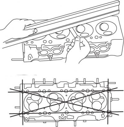
Pic. 3.28. Using a gauge bar and feeler gauge to check the flatness of the cylinder head mating surface and the direction in which measurements are to be taken
Using a feeler gauge and a gauge bar or a metal ruler, check the deviation of the mating surface of the cylinder head from flatness (pic. 3.28). If the curvature exceeds 0.15 mm along the length of the head, then the head must be ground in a car service workshop.
Check the condition of the valve seats in each combustion chamber. In the presence of shells, cracks and traces of burning, the head will need to be repaired in a car service workshop, since repairs are not possible at home.
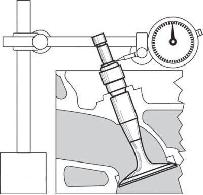
Pic. 3.29. Measuring the gap between the valve and the guide sleeve using a dial gauge
Check clearance between valve stems and guide bushings. Use a dial indicator to measure the lateral play of the valve stem inserted into the guide sleeve so that the valve protrudes from the seat by about 1.5 mm (pic. 3.29). If after this measurement there is a suspicion of increased wear of the guide bushing, and the result seems doubtful, then contact the service center, where a more accurate measurement will be carried out for a moderate fee.
Rocker arms
Inspect the surfaces of the rocker arms at the points of contact with the camshaft cams and valve stems, check for signs of wear, gouges and deep wear. Inspect also the working surfaces of the rocker shafts.
Inspect the inner surfaces of the holes for the shafts in the rocker arms, check for scoring and wear on them. Check the clearance between the shaft and the rocker by measuring the outer and inner diameters respectively, and compare the clearance with that specified in the technical data.
Replace severely worn or damaged parts.
Valves
Carefully inspect the valves, check for cracks, wear and burn marks. Check for cracks on the necks and stems. Check for deflection of the stems and wear of the ends of the valve stems. The presence of any defect indicates the need for repair of the valves in the body shop.
Measure the distance of the collar of each valve from the edge of the valve head and compare with the value given in the technical data. If this distance is less than the specified one, then the valve (both inlet and outlet) to be replaced.
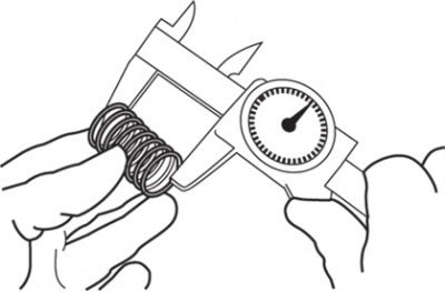
Pic. 3.30. Measuring the length of the valve spring in the free state
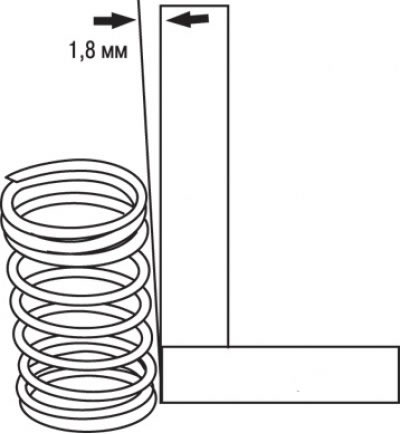
Pic. 3.31. Measuring the deviation of a spring from a vertical plane
Check for signs of wear on each valve spring (at the ends). Measure the free length of the spring (pic. 3.30) and compare it with the value given in the technical data. Springs with shrinkage, the length of which in the free state is less than the specified one, must be replaced (for any valve). Install the spring on a flat, level surface and check its deviation from the vertical plane (pic. 3.31).
Check for visible signs of wear and cracks on the retaining rings and crackers. Parts in doubt should be replaced, as their failure while the engine is running will cause serious damage.
If during inspection it turns out that the valve parts are in poor condition and excessively worn, which is usually observed in engines that have been overhauled, replace them.
If during the check it turns out that the wear of the parts does not exceed the permissible level, and the condition of the chamfers of the valves and seats is satisfactory, then all valve parts can be reinstalled on the cylinder head without additional repair work.