
MazBook.ru
English Русский
Български
Беларускі
Український
Српски
Hrvatski
Română
Polski
Slovenský
Magyar
• Bookmark • Sitemap • Contacts •   
Cars Opel Cars Ford Cars Volkswagen Cars Audi Cars Kia Cars Renault Cars Peugeot


Familia Capella Mazda3 Mazda6 CX-? Others Articles
Capella 3 (1982-1992, petrol) Capella 3 and 4 (1982-1992) Capella 4 (1987-1992) Capella 5 (1991-1997) Capella 6 (1997-2005, petrol)

Checking the technical condition of pistons and connecting rods (Mazda Capella GC)

  • Home
  • Mazda Capella
  • Capella GC (1982-1992)
  • Power unit
  • Engine overhaul (gasoline)
  • Checking the technical condition of pistons and connecting rods
0
Before checking, the connecting rods and pistons should be cleaned and the piston rings should be removed from the piston.

Caution! Old piston rings must always be replaced when disassembling the engine.
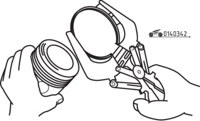

Figure 3.42. Using a special tool to remove piston rings

Figure 3.42. Using a special tool to remove piston rings


Carefully remove the rings from the piston using a special tool (figure 3.42). When removing the rings, be careful not to damage the piston surfaces. If you don't have a special tool, you can remove the rings using old feeler gauges or narrow metal strips. Carefully spread the ring, insert the plates between the ring and the piston and remove the ring by sliding it over the plates.

Repeat the operation with the remaining rings, making sure not to allow the bottom ring to enter the groove above. Since rings are subject to mandatory replacement, their accidental breakage should not be ignored, but the experience gained when removing rings will be very useful when installing new rings on the piston.

Remove carbon deposits from the piston crown. After removing the top rough layer of carbon, clean the piston crown with a brush or sandpaper on a cloth backing.


Never use a wire brush attached to a power drill to remove any remaining carbon deposits, as this can erode the soft alloy from which the pistons are cast.

Using a special tool, remove carbon deposits from the piston ring grooves. If such a device is not available, you can use an old broken piston ring. Remove only the carbon deposits, being careful not to remove any piston material. Be careful not to damage the ring groove seating surfaces. Be careful not to cut yourself, as the edges of the broken ring are sharp.

After removing the carbon deposits, thoroughly rinse the ring groove surfaces with solvent and dry thoroughly. Make sure the oil drain grooves where the oil scraper ring is installed are clean.

If there are no signs of significant wear and cylinder boring is not required, then the pistons should not be replaced. Normal wear is evident as uniform vertical wear on the piston friction surface and as a slight loosening of the upper compression ring fit.

Carefully inspect the piston skirt, piston pin bosses and piston ring seats for cracks.

Check for chips and scuffs on the friction surface of the piston skirt, traces of burnout in the central part of the piston crown, and burns on its crown. If chips and scuffs are found, this indicates frequent engine overheating, one of the causes of which may be a disruption in the normal combustion process of the fuel-air mixture. In this case, a thorough check of the lubrication and cooling systems is required. Burnout at the bottom of the piston indicates that the engine is running with an incorrect ignition timing setting. Piston crown burns are usually caused by abnormal combustion (detonation). If these defects are detected, the cause must be identified and corrected; otherwise, serious damage may occur.


Piston corrosion in the form of pits indicates penetration into the combustion chamber (and also in the crankcase) coolant. Here again, it is necessary to find and eliminate the cause, otherwise the repaired engine may fail.
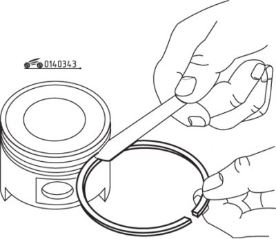
Figure 3.43. Measuring the piston ring height gap in the piston grooves

Figure 3.43. Measuring the piston ring height gap in the piston grooves


Measure the gap between the ring groove area and the piston ring by inserting a new ring into the groove and passing a feeler gauge between the groove and the ring (figure 3.43). Check the clearance in three or four places along the entire length of the groove. Make sure this ring fits the groove it will be installed in, as different grooves vary in size. If the clearance exceeds the maximum established, the piston should be replaced.

Check the clearance between the piston and cylinder by measuring the corresponding diameters. Make sure that measurements are taken on a pair of mating parts. Measure the piston skirt diameter. The clearance is determined by the difference between the diameters of the cylinder and the piston skirt. If the gap exceeds the maximum permissible value, the cylinder block must be bored, and the pistons and rings must be replaced with repair ones. The piston-to-cylinder clearance can also be measured, but with less accuracy, using a feeler gauge placed between the piston inserted into the cylinder and the cylinder.
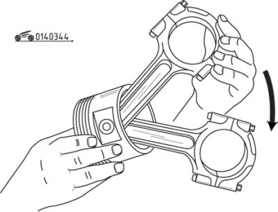


Figure 3.44. Rocking the piston and connecting rod in opposite directions to check the clearance…

Figure 3.44. Rocking the piston and connecting rod in opposite directions to check the clearance between the piston pin and the connecting rod head


Check the clearance between the piston pin and the connecting rod head by rocking the piston and connecting rod in opposite directions (figure 3.44). A noticeable amount of play will indicate an increased gap and the need to repair this connection. The piston assembly with the connecting rod must be submitted for repair to replace the piston pins, as well as to bore the connecting rod head and the piston hole to the repair dimensions.

The article is copied from the resource (MazBook)

If you need to remove the pistons from the connecting rods to replace the pistons or eliminate piston pin play, you need to take them to an auto repair shop. At the same time, it is necessary to check the bending and twisting of the connecting rods, for which the workshops have the necessary equipment. If new pistons or connecting rods need to be installed, the pistons should not be separated from the connecting rods.

Check the connecting rods for cracks or other damage. At this stage, remove the connecting rod bearing caps, take out the bearings, wipe the bearing seating surfaces on the connecting rod cap and on the connecting rod and check for cracks, scratches and burrs. After checking, reassemble the connecting rod, installing the bearings in place, and tighten the nuts by hand.
This article is available at: russian, bulgarian, belarusian, ukrainian, serbian, croatian, romanian, polish, slovak, hungarian
This text was checked by: Georgy Afanasyev
Share with friends on social networks:

Previous
Capella 3 and 4 » Engine overhaul (gasoline)
Next

Checking the technical condition of the camshaft
Checking the technical condition of the cylinder block
Cleaning the cylinder block
Removal the crankshaft
Removal pistons and connecting rods
Checking the technical condition of the crankshaft
Checking main and connecting rod bearings
Installing piston rings
Installing the crankshaft and checking the main bearing clearances
Installing pistons with connecting rods and checking connecting rod…
More articles on repairing other Mazda models
Checking the technical condition of parts Mazda Familia 5 (1985-1989)
Checking the connecting rod side clearance Mazda3 BK (2003-2009)
Checking the connecting rod side clearance Mazda6 GG (2002-2008)
Checking the connecting rods of the cylinder block Mazda CX-5KE (2012-2017)
Connecting rods and pistons Mazda BT-50 (1) (2006-2011)
Link in different formats to this article
Comments and feedback from visitors
No comments yet


How much will 47 + 27 ?


Capella 6 (1997-2005, petrol) 
  • General information
  • Introduction to guide
  • User manual
  • Troubleshooting
  • Maintenance
  • Power unit
  • 4-cylinder engines
  • 6-cylinder engines
  • Engine overhaul
  • Cooling and ventilation
  • Power and exhaust systems
  • Engine electrics
  • Control system
  • Transmission
  • Mechanical gearbox
  • Automatic gearbox
  • Clutch and drive shafts
  • Chassis
  • Brake system
  • Car suspension
  • Steering
  • Body
  • Exterior (external elements)
  • Interior (internal elements)
  • Doors, windows and locks
  • Electrical equipment
  • Equipment and devices
  • Electrical circuits
Capella 5 (1991-1997) 
  • General information
  • User manual
  • Maintenance
  • Helpful hints
  • Power unit
  • Petrol engines 1.6 and 1.8
  • Petrol engines 2.0
  • 2.5 petrol engines
  • Overhaul engines 1.6 and 1.8
  • Overhaul engines 2.0 and 2.5
  • Diesel engine 2.0
  • Engine electrics
  • Cooling system
  • Air conditioner
  • Carburetor Nikki 30/34
  • Power system (1.6 and 1.8)
  • Power system (2.0 and 2.5)
  • Control system
  • Transmission
  • Mechanical gearbox
  • Automatic gearbox
  • Clutch and axles
  • Chassis
  • Brake system
  • Suspension and wheels
  • Steering
  • Body
  • Exterior (external elements)
  • Interior (internal elements)
  • Doors and windows
  • Electrical equipment
  • Equipment and devices
  • Electrical circuits
Capella 4 (1987-1992) 
  • General information
  • Introduction to manual
  • Vehicle specifications
  • Power unit
  • Engine repair
  • Lubrication system
  • Cooling system
  • Fuel system (carburetor)
  • Fuel injection (FE)
  • Fuel injection (DOHC)
  • Fuel system (diesel)
  • Ignition system
  • Transmission
  • Clutch
  • Gearbox
  • Drive shafts
  • Chassis
  • Front suspension
  • Rear suspension
  • Steering system
  • Brake system
  • Electrical equipment
  • Equipment and devices
  • Electrical circuits
Capella 3 and 4 (1982-1992) 
  • General information
  • User manual
  • Maintenance
  • Power unit
  • Gasoline engine
  • Engine overhaul (gasoline)
  • Diesel engine
  • Cooling and heating
  • Supply system
  • Ignition system
  • Emission reduction
  • Transmission
  • Clutch
  • Mechanical gearbox
  • Automatic gearbox
  • Drive shafts
  • Chassis
  • Brake system
  • Suspension and wheels
  • Steering
  • Body
  • Exterior (external elements)
  • Interior (internal elements)
  • Electrical equipment
  • Equipment and devices
  • Power devices
  • Electrical circuits
Capella 3 (1982-1992, petrol) 
  • General information
  • User manual
  • Maintenance
  • Troubleshooting
  • Late models
  • Power unit
  • Engine in car
  • Engine overhaul
  • Cooling and heating system
  • Fuel and exhaust system
  • Engine electrical system
  • Emission control system
  • Transmission
  • Mechanical gearbox
  • Automatic gearbox
  • Clutch and drive shafts
  • Chassis
  • Brake system
  • Suspension and wheels
  • Steering
  • Body
  • Exterior (external elements)
  • Interior (internal elements)
  • Electrical equipment
  • Equipment and devices
  • Lighting and lamps
  • Electrical circuits
MazBook.ru © 2018–2026 · Mobile version · Articles and news · Sitemap: EN BG BY UA RS HR RO PL SK HU · Feedback · Site search · Add to bookmarks Familia 5 (BF) · Familia 6 (BG) · Capella 3 (GC) · Capella 3 and 4 (GC) · Capella 4 (GD) · Capella 5 (GE) · Capella 6 (GF) · Mazda3 BK · Mazda6 GG · CX-5KE · Mazda 121 (3) · Mazda BT-50 (1) ·
By continuing to use the site, you agree to the use of cookies 🔐