


Position the cylinder block so that its bottom is pointing up.
Loosen the main bearing cap bolts and lay them out so that they can be reinstalled later.
Remove the main bearing shells from the covers and cylinder block if they are still in place. Wipe the surfaces of the bottom and top earbuds with a clean, lint-free cloth. These parts must be kept completely clean.
Clean the outer surface of the new main bearings and install them in the cylinder block seats. Insert the appropriate matching inserts into the covers. Make sure that the tab on the liner matches the notch on the block or on the cover.
In addition, the oil passage hole in the block must be aligned with the lubrication hole of the bushing. It is not allowed to install the insert in place by hammer blows, scratching. At this stage, lubrication of the liner is not required.
The insert with flanges must be installed in slot No. 3.
Wipe the working surfaces of the liners in the block and the crankshaft main journals with a clean, lint-free rag. Check or clean the crankshaft oil passages, as now the only way for any contamination to escape is through the new bearings.
With full confidence in the cleanliness of the shaft, carefully place it in place on the main bearing shells (it is recommended to perform the operation with an assistant).
Before the final installation of the shaft, it is necessary to check the lubrication gap in the main bearings.
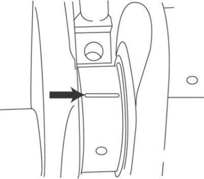
Pic. 3.51. The location of the segment of the calibrated plastic rod when measuring the clearance of the main bearings of the crankshaft
Prepare several pieces of a calibrated plastic rod, the length of which is slightly less than the width of the main bearings, and place one piece on each main journal of the crankshaft parallel to its axis (pic. 3.51).
Clean the surfaces of the inserts in the covers and install the covers in place (don't mix them up) so that the arrows point towards the front of the engine. It is not allowed to touch the plastic rods.
Tighten the cap bolts in three steps to the required torque, starting from the center bearing and continuing to the ends of the shaft. Shaft rotation is not allowed during this operation.
Loosen the cap bolts and carefully lift the main bearing caps. Arrange the covers in the order corresponding to their installation location. It is unacceptable to disturb the position of the rods and rotate the crankshaft. If the cap is difficult to remove, loosen it by tapping lightly on the side with a soft-faced hammer.
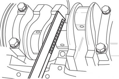
Pic. 3.52. Using the scale printed on the package to measure the width of a deformed calibrated plastic rod
Compare the thickness of each of the deformed plastic rods with the scale on the packaging and determine the gap (pic. 3.52). Compare with the required value.
If the clearance is not as specified, recheck to make sure the main bearings are properly sized. Also, make sure that there is no dirt or oil between the bearings and the seating surfaces when measuring.
Carefully remove the remnants of the plastic rod from the journals of the crankshaft and / or from the surfaces of the main bearings. Avoid damage to main bearing surfaces.
Carefully remove the crankshaft from the cylinder block. Clean the running surfaces of the main bearings and apply a thin, even coat of high quality molybdenum disulphide grease or engine assembly oil to each of them. Be sure to lubricate the thrust flange surfaces of the shaft and the friction surface of the thrust bearing.
Make sure the crankshaft journals are clean, then install the crankshaft into the cylinder block. Clean the bearing surfaces in the caps and apply a thin coat of molybdenum disulphide grease to each. Reinstall the covers so that the arrows point towards the front of the engine. Install the bolts and tighten them to the required torque, starting from the center bearing and moving towards the ends of the shaft. Tighten the bolts in three steps.
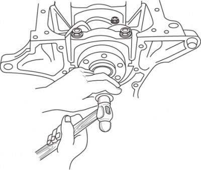
Pic. 3.53. Using a mandrel and a hammer to install the pilot bearing into the end of the crankshaft
On models with automatic transmission, install a new guide bearing into the end of the crankshaft. Lubricate the shaft cavity and bearing outer surface with clean engine oil, install the bearing. The landing of the bearing is carried out by light blows of the hammer on the mandrel (pic. 3.53). Put grease in the bearing.
Turn the crankshaft several times by hand - the shaft should rotate without noticeable jamming.
At the last stage, check the axial play of the crankshaft with a pointer indicator.