


Before removing the connecting rods, check their axial play. Install the indicator so that its leg coincides with the axis of the crankshaft and touches the side surface of the first connecting rod cover.
Pull the connecting rod towards the rear of the engine with maximum force and in this position set the indicator scale to zero. Then move the crank forward to its maximum distance and read the indicator reading. Axial play is equal to the distance the connecting rod has moved. If the connecting rod axial play exceeds the value given in the technical data, it must be replaced. Measure the axial play of the other connecting rods in exactly the same way.
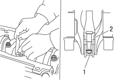
Figure 3.32. Using a feeler gauge to measure the connecting rod axial play: 1 – connecting rod cover; 2 – place of backlash measurement
Alternatively, you can use another method to measure axial play by inserting a feeler gauge between the connecting rod and the surface of the crankshaft thrust flange (figure 3.32). Increase the thickness of the feeler gauge until the play disappears. The amount of axial play is equal to the final thickness of the feeler gauge.
Check for marks on the connecting rods and connecting rod caps. If there are no marks, then punch them so that the number of marks corresponds to the number of the cylinder in which this connecting rod is installed.
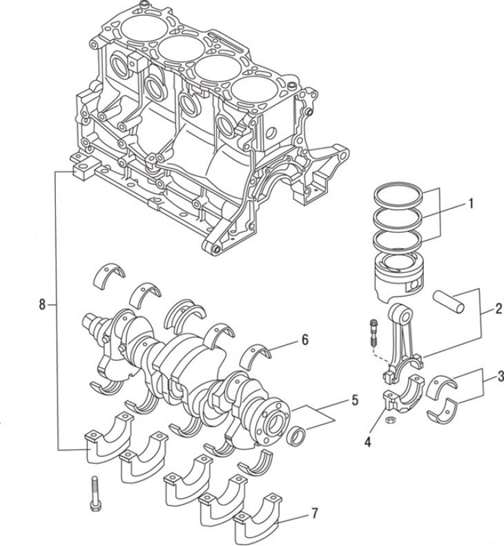
Figure 3.33. Cylinder block, crankshaft, bearings and connecting rods: 1 – piston rings; 2 – connecting rod and piston pin; 3 – connecting rod bearing shells; 4 – connecting rod cover; 5 – crankshaft and needle bearing; 6 – main bearing shell; 7 – main bearing cap; 8 – cylinder block
Loosen the nuts by 1-2 turns. Remove the connecting rod cap from the first cylinder along with the connecting rod bearing (figure 3.33). Do not remove the connecting rod bearing from the cover. Place pieces of rubber or plastic hoses on the connecting rod cap mounting bolts to avoid damaging the crankshaft journal and cylinder walls when removing the connecting rod, and push the piston assembly with the connecting rod out through the top of the cylinder. To do this, use a wooden spacer, resting it against the upper connecting rod bearing. If you feel resistance when removing the piston, check again that the flange has been completely removed from the top of the cylinder.
Repeat the procedure for the remaining cylinders. After the pistons and connecting rods have been removed from the cylinders, remove the connecting rod caps, take out the connecting rod bearings, install the caps in place and tighten the nuts by hand.
It is recommended to remove the connecting rod bearings only before assembly, thus preventing accidental damage to their working surfaces.
Original version of the article on the website MAZBOOK.RU