
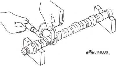
Pic. 3.38. Measuring the height of the camshaft cams
Measure the height of the cams with a micrometer and compare with the standard value to determine their wear (pic. 3.38).
Check the cams for metal chipping, scratches, gouges, wear, and uneven wear. If the cams are in good condition and the diameters of the cams do not exceed the established norm, then its further operation is permissible.
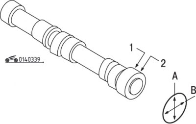
Pic. 3.39. Places for measuring the diameter of the front camshaft journal
Measure the diameter of the middle journals with a micrometer to determine their wear and ovality. If the ovality exceeds 0.5 mm, then the camshaft must be replaced. In two diametrically opposite directions, measure the diameter of the front journal and the inner diameter of the front cover, compare with the standard value to determine the degree of wear (pic. 3.39).
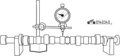
Pic. 3.40. Checking Camshaft Runout with a Dial Gauge
Check the runout of the camshaft with a pointer indicator, having previously installed the camshaft on the prisms (pic. 3.40).
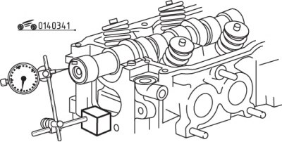
Pic. 3.41. Measuring the camshaft end play with a dial indicator
Establish a camshaft on a head of the block of cylinders and a dial indicator measure axial backlash, having displaced a shaft against the stop back, and then forward, as it is shown in fig. 3.41.
The camshaft lubrication clearance is checked at the final assembly stage, after the cylinder head has been installed and the bolts have been tightened. The mating surfaces of the camshaft bearings must be clean and free from oil. Lay pieces of a calibrated plastic rod on the surface of the camshaft journals, placing them parallel to the axis, and tighten the bearing cap bolts to the required torque. Loosen the bolts and determine the lubrication gap by the amount of deformation of the calibrated plastic rod, using the scale printed on its packaging. If the clearance exceeds the specified limit, the cylinder head and camshaft bearing cap must be replaced.