
MazBook.ru
English Русский
Български
Беларускі
Український
Српски
Hrvatski
Română
Polski
Slovenský
Magyar
• Bookmark • Sitemap • Contacts •   
Cars Opel Cars Ford Cars Volkswagen Cars Audi Cars Kia Cars Renault Cars Peugeot


Familia Capella Mazda3 Mazda6 CX-? Others Articles
Capella 3 (1982-1992, petrol) Capella 3 and 4 (1982-1992) Capella 4 (1987-1992) Capella 5 (1991-1997) Capella 6 (1997-2005, petrol)

Installing piston rings (Mazda Capella GC)

  • Home
  • Mazda Capella
  • Capella GC (1982-1992)
  • Power unit
  • Engine overhaul (gasoline)
  • Installing piston rings
0
Before installing new piston rings, you need to check the gap in the ring joints. It is assumed that the clearance between the ring and the groove pad has already been checked and meets the requirements.

Lay out the piston assemblies with connecting rods and new piston rings in such a way that the set of rings corresponds to the given cylinder on which the gap in the lock will be measured.
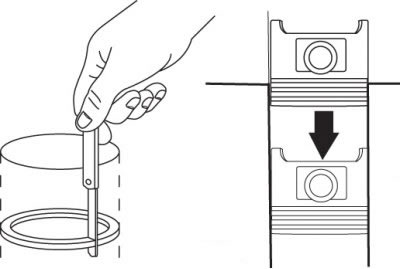
Figure 3.46. Measuring the gap in the piston ring joint

Figure 3.46. Measuring the gap in the piston ring joint


Insert the top ring into the first cylinder and push it in with the piston crown so that the ring inside the cylinder becomes perpendicular to its axis. The ring must be located at the bottom of the cylinder in a position corresponding to the bottom dead center. The gap in the piston ring lock is measured with a feeler gauge (figure 3.46). Compare the result with the required value.

If the gap is greater or less than specified, repeat the measurement to ensure the ring can be installed.

(The original article is on: «mazbook.ru»)

If the gap is too small, it must be increased, otherwise, during engine operation, the ends of the ring will connect, which can cause serious damage. The gap in the piston ring lock can be increased by carefully filing the ends with a thin file. Place the file in a vice with soft jaws and carefully move the ring over it, removing excess material.


The gap may exceed the established one, but should not be more than 1 mm.

The measurement should be repeated to ensure the ring fits properly.

Repeat the measurements for each ring installed in the first cylinder, as well as for the remaining rings installed in the other cylinders.

After measuring the ring gaps and adjusting them, the rings can be installed on the pistons.

The oil scraper ring is installed first (the lowest on the piston).
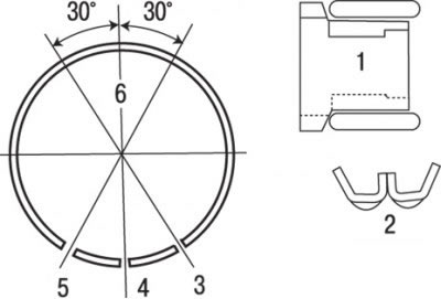
Figure 3.47. Location of oil scraper ring elements and locks: 1 – oil scraper ring; 2 – oil scraper…

Figure 3.47. Location of oil scraper ring elements and locks: 1 – oil scraper ring; 2 – oil scraper ring (expander); 3 – lower guide; 4 – expander; 5 – upper guide; 6 – piston pin
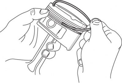

Figure 3.48. Installing oil scraper ring components

Figure 3.48. Installing oil scraper ring components


This ring consists of three elements. Install the spacer/expander into the groove (figure 3.47), then install the lower oil scraper ring guide. When installing the guides, do not use a ring installation tool, as this may cause them to break. Insert one end of the guide into the piston groove between the separator and the horizontal surface of the groove and, holding it firmly, insert the other end of the ring into the groove with your finger (figure 3.48). Install the second guide in the same way.


After installing all the oil scraper ring components, make sure that the upper and lower guides rotate freely in the groove. Arrange the oil scraper ring locks in accordance with the drawing 3.47.

The middle ring is installed next. It has an "R" mark stamped on it, which should be directed towards the bottom of the piston.

Caution! Always follow the instructions on the piston ring packaging; different manufacturers may have different markings.


Caution! Do not confuse the upper and lower compression rings, as they have different cross-sectional profiles.
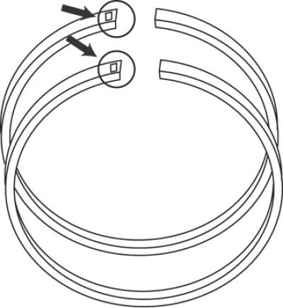

Figure 3.49. Location of marks on compression piston rings

Figure 3.49. Location of marks on compression piston rings


Install the piston ring installer, ensure the marks are facing the piston bottom, and move the corresponding ring into the piston center groove (figure 3.49). Do not spread the ends of the ring more than is required for it to pass over the piston. Instead of the device, you can use metal strips.
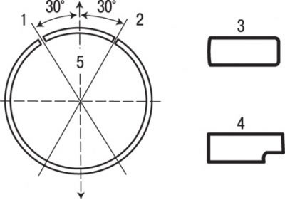
Figure 3.50. Installation position of compression rings and location of their locks: 1 – upper…

Figure 3.50. Installation position of compression rings and location of their locks: 1 – upper compression ring lock; 2 – lower compression ring lock; 3 – upper compression ring; 4 – lower compression ring; 5 – piston pin


Install the upper compression ring in the same way. Make sure the marks are facing up. Do not confuse the upper and lower compression rings. Arrange the ring locks according to the drawing 3.50.
This article is available at: russian, bulgarian, belarusian, ukrainian, serbian, croatian, romanian, polish, slovak, hungarian
This text was checked by: Georgy Afanasyev
Share with friends on social networks:

Previous
Capella 3 and 4 » Engine overhaul (gasoline)
Next

Checking main and connecting rod bearings
Checking the technical condition of the crankshaft
Checking the technical condition of pistons and connecting rods
Checking the technical condition of the camshaft
Checking the technical condition of the cylinder block
Installing the crankshaft and checking the main bearing clearances
Installing pistons with connecting rods and checking connecting rod…
Installing the rear oil seal and rear cover
Engine assembly sequence during major repairs
Starting the engine after repair and running it in
More articles on repairing other Mazda models
Installing the cylinder head Mazda Familia 5 (1985-1989)
Installing piston rings Mazda3 BK (2003-2009)
Installing piston rings Mazda6 GG (2002-2008)
Checking the piston rings of the cylinder block Mazda CX-5KE (2012-2017)
Installing a timing belt Mazda 121 (3) (1996-2003)
Link in different formats to this article
Comments and feedback from visitors
No comments yet


How much will 16 + 46 ?


Capella 6 (1997-2005, petrol) 
  • General information
  • Introduction to guide
  • User manual
  • Troubleshooting
  • Maintenance
  • Power unit
  • 4-cylinder engines
  • 6-cylinder engines
  • Engine overhaul
  • Cooling and ventilation
  • Power and exhaust systems
  • Engine electrics
  • Control system
  • Transmission
  • Mechanical gearbox
  • Automatic gearbox
  • Clutch and drive shafts
  • Chassis
  • Brake system
  • Car suspension
  • Steering
  • Body
  • Exterior (external elements)
  • Interior (internal elements)
  • Doors, windows and locks
  • Electrical equipment
  • Equipment and devices
  • Electrical circuits
Capella 5 (1991-1997) 
  • General information
  • User manual
  • Maintenance
  • Helpful hints
  • Power unit
  • Petrol engines 1.6 and 1.8
  • Petrol engines 2.0
  • 2.5 petrol engines
  • Overhaul engines 1.6 and 1.8
  • Overhaul engines 2.0 and 2.5
  • Diesel engine 2.0
  • Engine electrics
  • Cooling system
  • Air conditioner
  • Carburetor Nikki 30/34
  • Power system (1.6 and 1.8)
  • Power system (2.0 and 2.5)
  • Control system
  • Transmission
  • Mechanical gearbox
  • Automatic gearbox
  • Clutch and axles
  • Chassis
  • Brake system
  • Suspension and wheels
  • Steering
  • Body
  • Exterior (external elements)
  • Interior (internal elements)
  • Doors and windows
  • Electrical equipment
  • Equipment and devices
  • Electrical circuits
Capella 4 (1987-1992) 
  • General information
  • Introduction to manual
  • Vehicle specifications
  • Power unit
  • Engine repair
  • Lubrication system
  • Cooling system
  • Fuel system (carburetor)
  • Fuel injection (FE)
  • Fuel injection (DOHC)
  • Fuel system (diesel)
  • Ignition system
  • Transmission
  • Clutch
  • Gearbox
  • Drive shafts
  • Chassis
  • Front suspension
  • Rear suspension
  • Steering system
  • Brake system
  • Electrical equipment
  • Equipment and devices
  • Electrical circuits
Capella 3 and 4 (1982-1992) 
  • General information
  • User manual
  • Maintenance
  • Power unit
  • Gasoline engine
  • Engine overhaul (gasoline)
  • Diesel engine
  • Cooling and heating
  • Supply system
  • Ignition system
  • Emission reduction
  • Transmission
  • Clutch
  • Mechanical gearbox
  • Automatic gearbox
  • Drive shafts
  • Chassis
  • Brake system
  • Suspension and wheels
  • Steering
  • Body
  • Exterior (external elements)
  • Interior (internal elements)
  • Electrical equipment
  • Equipment and devices
  • Power devices
  • Electrical circuits
Capella 3 (1982-1992, petrol) 
  • General information
  • User manual
  • Maintenance
  • Troubleshooting
  • Late models
  • Power unit
  • Engine in car
  • Engine overhaul
  • Cooling and heating system
  • Fuel and exhaust system
  • Engine electrical system
  • Emission control system
  • Transmission
  • Mechanical gearbox
  • Automatic gearbox
  • Clutch and drive shafts
  • Chassis
  • Brake system
  • Suspension and wheels
  • Steering
  • Body
  • Exterior (external elements)
  • Interior (internal elements)
  • Electrical equipment
  • Equipment and devices
  • Lighting and lamps
  • Electrical circuits
MazBook.ru © 2018–2026 · Mobile version · Articles and news · Sitemap: EN BG BY UA RS HR RO PL SK HU · Feedback · Site search · Add to bookmarks Familia 5 (BF) · Familia 6 (BG) · Capella 3 (GC) · Capella 3 and 4 (GC) · Capella 4 (GD) · Capella 5 (GE) · Capella 6 (GF) · Mazda3 BK · Mazda6 GG · CX-5KE · Mazda 121 (3) · Mazda BT-50 (1) ·
By continuing to use the site, you agree to the use of cookies 🔐