
Remove the bearing cap from the connecting rod of the first cylinder. Remove the old connecting rod bearing shells and wipe the bearing seating surfaces in the connecting rod and cap with a clean, lint-free cloth.
These surfaces must always be absolutely clean.
Wipe the back surface of the upper connecting rod bearing and place it in its place in the connecting rod. Make sure the tab on the bushing lines up with the notch on the connecting rod. To fit the liner, it is unacceptable to use a hammer: extreme care must be taken not to damage the working surface of the liner.
At this stage, lubrication of the liner is not required.
Wipe the back surface of the lower bearing and insert it into the connecting rod cap. Again, make sure that the tab on the liner matches the recess on the connecting rod cap, do not lubricate the liner. It is very important that the mating surfaces of the bushing and connecting rod are absolutely clean during the assembly process, without traces of oil.
Arrange locks of piston rings according to fig. 3.50, then put pieces of rubber hoses on the bolts of the connecting rod caps.
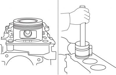
Lubricate the pistons and rings with clean engine oil and fit a piston ring compression tool onto the piston. The length of the protruding section of the piston skirt should be approximately 6 mm to ensure proper piston entry into the cylinder. Rings should be compressed as much as possible.
Turn the crankshaft to the bottom dead center position in the first cylinder and lubricate the cylinder walls with engine oil.
Pic. 3.54. Installing the piston in the cylinder: label «F» must point towards the front of the engine (crankshaft pulley)
Turn the piston with the connecting rod so that the arrow on the piston points towards the front of the engine; carefully insert the piston with the connecting rod into the first cylinder until the mandrel stops against the cylinder block. Lightly tap the top edge of the mandrel to ensure even contact with the plane of the cylinder block around the entire circumference. If there is no mark in the form of an arrow or notch on the piston crown, before installing the mandrel, orient the piston so that the mark «F» on the boss of the pin was directed towards the front of the engine (crankshaft pulley) (pic. 3.54).
Gently tap the piston crown with the wooden handle of the hammer, guiding the connecting rod against the appropriate crankshaft journal. Piston rings can pop out of the mandrel before entering the cylinder, so the mandrel must always be pressed against the cylinder block. Perform this operation carefully; Stop work immediately if you feel any resistance as the piston enters the cylinder. Determine the cause of the sticking and correct it, then proceed with the installation of the piston in the cylinder. Do not apply force when installing the piston in the cylinder, as you can break the rings or the piston.
After installing the pistons in the cylinder, it is necessary to measure the clearance (between connecting rod bearings and shaft journals) and only then finally install the covers.
Prepare a piece of a calibrated plastic rod, the length of which is slightly less than the width of the connecting rod bearing, and place it on the connecting rod journal of the first cylinder parallel to the axis of the crankshaft. The pin must not block the oil hole in the shaft journal.
Clean the surfaces in the cover adjacent to the liners, remove the hoses from the cover bolts and install the cover. Make sure the marks on the cap and connecting rod are on the same side. Install the nuts and tighten them to the required torque in three steps. During this operation, the rotation of the crankshaft is not allowed.
Carefully remove the covers without damaging the plastic stem. Compare the thickness of the deformed plastic rod with the scale on the packaging and determine the lubrication gap. Compare with the required value. If the clearance is not correct, recheck to make sure the connecting rod bearings are the correct size. Also check the diameter of the inner bore in the connecting rod and make sure there is no dirt or oil between the bearings and the seating surfaces when measuring the clearance.
Carefully remove the remains of the deformed rod from the journals of the crankshaft and / or from the surfaces of the connecting rod bearings. Be careful not to damage the surfaces of the connecting rod bearings, remove the residue with your index finger or a wooden spatula. Ensure that the connecting rod bearing surfaces are absolutely clean, apply a thin, even coat of high quality molybdenum disulphide grease or engine assembly oil to the bearing shells. To access the surface of the upper connecting rod bearing, you will have to push the piston into the cylinder, after putting hose sections on the cover bolts.
Pull the connecting rod to the crankshaft journal, remove the hoses from the cap bolts, install the caps and tighten the nuts to the required torque. Tighten the nuts in three steps.
Repeat the above procedure for the pistons and connecting rods of the other cylinders. During assembly, keep the mating surfaces of the connecting rod and connecting rod bearings clean. Make sure that each piston corresponds to this cylinder, and the notch, arrow or mark «F» when installing the piston in the cylinder were directed towards the front of the engine. Remember that the cylinder must be generously lubricated before installing the ring compression mandrel.
At the final assembly of connecting rods with covers, it is necessary to lubricate the working surfaces of the bearings.
After the pistons with connecting rods are correctly installed, turn the crankshaft by hand a few turns, the shaft should rotate without jamming.
At the last stage of assembly, it is necessary to check the axial play of the connecting rod.