
It is assumed that the gap between the ring and the seat of the groove has already been checked and is in accordance with the norms.
Lay out the piston and connecting rod assemblies and the new piston rings in such an order that the set of rings matches the given cylinder on which the joint clearance will be measured.
Insert the upper ring into the first cylinder and push the piston head inward, so that the ring inside the cylinder becomes perpendicular to its axis. The ring should be at the bottom of the cylinder, in the position corresponding to the bottom dead center.
Piston ring gap is measured with a feeler gauge. Compare the result with the set value.
If the gap is greater or less than the specified, then repeat the measurement to make sure that the ring can be installed.
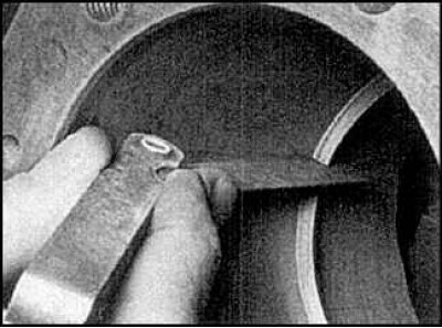
If the gap is too small, then it must be increased, because otherwise, during the operation of the engine, the ends of the ring will close, which can cause serious damage. The clearance at the junction of the piston ring can be increased by carefully filing the ends with a thin file. Clamp the file in a vise with soft jaws and carefully move the ring along it, removing excess material.
The gap may exceed the specified, but should be no more than 1 mm.
The measurement should be repeated to ensure the fit of the ring.
Repeat the measurements for each ring installed in the first cylinder, as well as for each of the rings installed in other cylinders.
After measuring the gaps at the junction of the rings and adjusting it, the rings can be installed on the pistons.
The oil scraper ring is installed first (the bottom of the piston).
This ring is made up of three parts.
Install the spacer/expander into the groove.
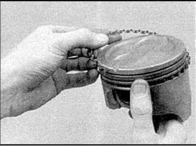
Install the lower oil ring guide. When installing the guides, it is impossible to use a device for dressing rings, as they may break. Insert one end of the guide into the groove of the piston, between the spacer and the horizontal platform of the groove, and, holding it firmly, slide the other end of the ring into the groove with your finger. Install the second guide in the same way.
After installing all parts of the oil scraper ring, make sure that the upper and lower guides turn freely in the groove. Arrange the joints of the oil scraper ring in accordance with the figure.
The middle ring is installed next (number 2). This ring is stamped "R", which should be facing the piston crown.
Attention! Always proceed according to the instructions on the piston ring packaging, different manufacturers may have different designations. Do not confuse the top and bottom compression rings as they have different cross-sectional profiles.
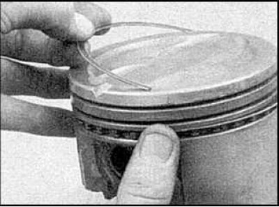
Install the piston ring fitting tool, make sure the marks are facing the piston crown and move the appropriate ring into the middle groove of the piston. Do not spread the ring joints further than required to pass over the piston. Instead of a fixture, you can use metal strips.
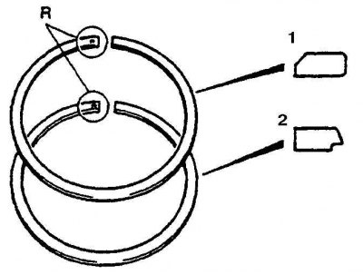
Install the top compression ring in the same way. Make sure the labels are pointing up. Do not mix up the top compression ring (1) with the bottom. compression ring (2). Arrange the joints of the rings in accordance with the figure.