


Removal and installation
For easier access, remove the ignition distributor and air cleaner intake pipe.
Disconnect the contact connector from the electric motor thermal switch.
Drain the cooling system to a level that matches the bottom of the upper radiator hose. To do this, unscrew the drain plug located at the bottom of the radiator.
Loosen the clamp and remove the upper radiator hose.
Remove the bolts and remove the fan motor assembly with the guide casing.
Installation is carried out in the reverse order of removal, taking into account the following.
Add antifreeze to the cooling system, connect the wire to the negative terminal of the battery and check that the fan turns on when the engine warms up.
Checking and repairing the radiator fan
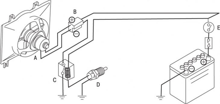
Figure 5.4. Radiator fan connection diagram: A – electric motor; B – contact connector; C – intermediate relay; D – thermal switch; E – ignition switch
The cooling system fan consists of an electric motor and an impeller mounted on a guide casing, which is bolted to the radiator; a relay for turning on the fan, mounted on the left inner mudguard, and a thermal switch screwed into the thermostat housing (figure 5.4).
When the temperature rises to the threshold value (97°C), the thermal switch contacts open and the fan motor is switched on via an intermediate relay. When the temperature drops to 90°C, the thermal switch contacts close and the electric motor switches off. The relay contacts are normally closed, i.e., to turn off the electric motor, current must flow through the intermediate relay winding.
Data provided by the website: MazBook.ru