


Valve drive
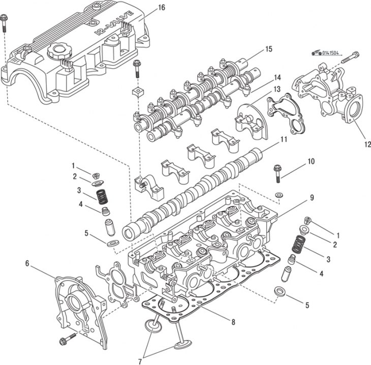
Figure 15.4. Cylinder head (12-valve): 1 – crackers; 2 – upper valve plate; 3 – spring; 4 – oil deflector cap; 5 – lower valve plate; 6 – front cover; 7 – valves; 8 – cylinder head gasket; 9 – cylinder head; 10 – cylinder head mounting bolt; 11 – camshaft; 12 – back cover; 13 – camshaft bearing caps; 14 – hydraulic valve clearance compensator; 15 – valve control mechanism assembly; 16 – cylinder head cover
The disassembly process is complicated by the fact that the camshaft bearing caps are located under the rocker shafts, and hydraulic valve clearance compensators are built into the rocker arms (figure 15.4).
After removing the rocker arms and shafts, remove the camshaft bearing caps
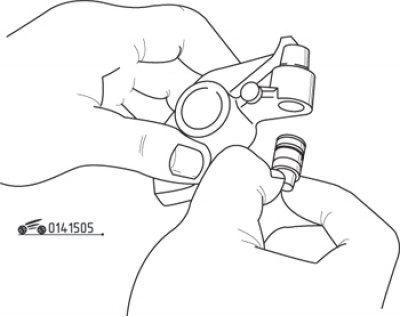
Figure 15.5. Removing the hydraulic valve clearance compensator from the rocker arm
Check the condition of the working surfaces of the hydraulic valve clearance compensator. Take them out with your fingers (figure 15.5). Do not remove the hydraulic valve lifter unless necessary, as the O-rings can be easily damaged.
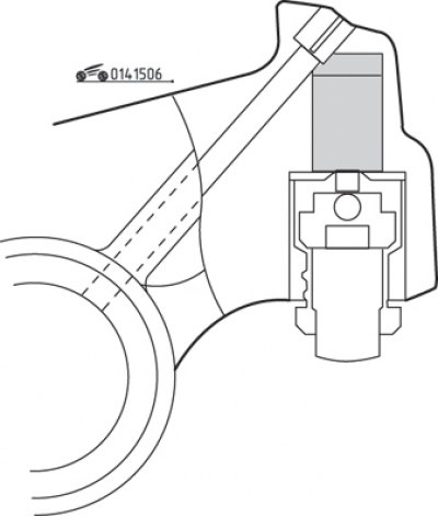
Figure 15.6. Installing the hydraulic valve clearance compensator after filling the rocker arm cavity with clean engine oil
Fill the cavity for the hydraulic valve clearance compensator with clean engine oil and carefully, so as not to damage the O-rings, insert the hydraulic compensator into the rocker arm (figure 15.6).
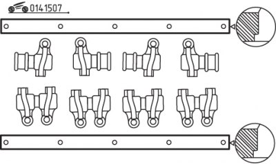
Figure 15.7. Correct placement of rocker arms
(The original text is published on: MAZBOOK.ru)
Assemble the rocker arms with the shafts so that the grooves on the ends of the shafts are directed towards the rear of the engine (the intake valve shafts have twice as many oil passages as the exhaust valve shafts) (figure 15.7).
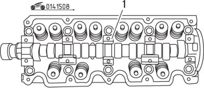
Figure 15.8. Location of the oil channel (1) on the bearing cover No. 3 of the camshaft
After installing the camshaft, install the bearing caps with the arrows pointing toward the front of the engine. The oil channel on the bearing cover No. 3 should be on the side shown in the figure 15.8.
Install the rocker arm assemblies, ensuring that the rocker arms and spacer bushings are correctly oriented and that there is no contact with the camshaft bearing caps.