
When troubleshooting the exhaust emissions system, you should also check the fuel supply and exhaust systems, electrical equipment, as they are interconnected.
The air injection system consists of check and reed valves, which are mounted on the air filter housing. Turbocharged engines, in addition to the valve on the air filter housing, have additional remote reed valves mounted on the right shock absorber cup.
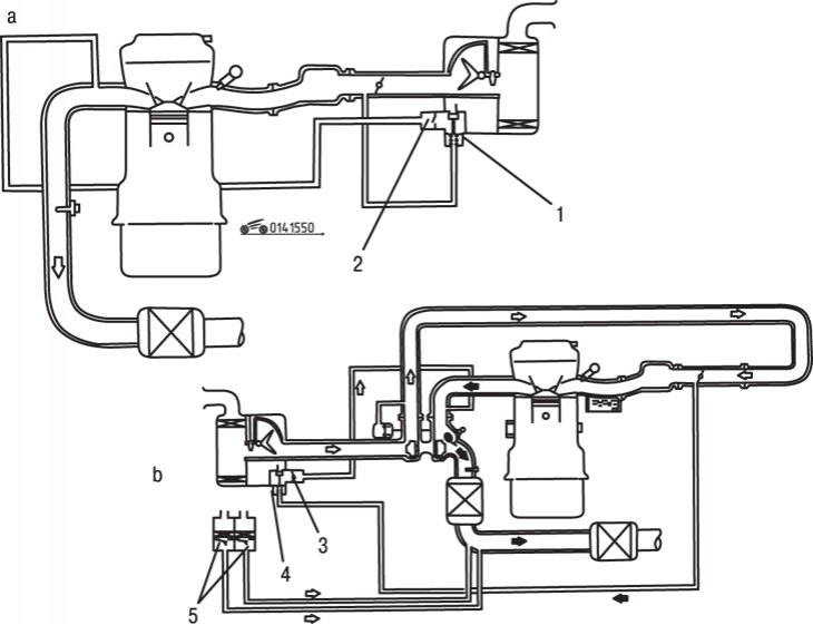
Pic. 15.50. Diagram of the air injection system: a - engines without turbocharging; b - turbocharged engines; 1, 4 - control valves; 2, 3, 5 - reed valves
When the vacuum in the intake manifold reaches a certain level, the control valve opens and fresh air is sucked into the manifold due to a sharp increase in the exhaust gas flow rate (pic. 15.50). At the same time, afterburning of the remains of unburned fuel is ensured and the content of hydrocarbons in the exhaust gases is reduced. The two remote valves in turbocharged vehicles only operate when there is a strong enough flow of exhaust gases to draw air through these valves (as a rule, at an engine speed of 2500 min-1).
Checking valves
To check the air injection system, remove the air filter cover and run the engine at idle. A tangible flow of air should be sucked into the air channel, which is checked with a piece of paper held up to the hole.
Bring the engine speed to 2500 min-1 and check that there is no air intake. Visually check that exhaust gases do not escape through the opening.
If the system is not working properly, check the air check valve and reed valve.
To check the air control valve, remove it from the housing and connect it to a vacuum pump. Gradually pump out the air and watch the rod, which should extend with a vacuum of 180-280 mm Hg. Art. If the valve fails the test or is leaking, replace it.
To check the reed valve, warm up the engine and set it to idle. Connect the vacuum pump and pump out the air to a pressure of 500 mm Hg. Art. Lift the air filter cover and check if air is being sucked into the opening. Increase the engine speed to 2500 min-1 and check that there is no exhaust gas coming out. If the valve fails the test, replace it.
For testing remote reed valves (only for turbocharged engines) bring the engine speed to 2500 min-1 and check the intake of air into the channels. Make sure there is no exhaust gas outlet. If both valves fail the test, replace them.
Valve replacement
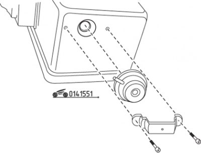
Pic. 15.51. Control valve mounting elements
To replace the check valve, unscrew the two screws and remove the check valve from the air filter housing (pic. 15.51). Installation is carried out in the reverse order of removal.
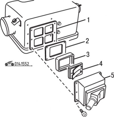
Pic. 15.52. Reed valve fastening elements: 1 - gasket; 2 - mounting plate; 3 - rubber insert; 4 - reed valve; 5 - body
To replace the reed valve, remove the air filter cover. Remove the mounting plate, rubber insert, gasket and reed valve from the filter housing (pic. 15.52). Check the condition of the insert, if there are cracks or other signs of destruction, replace the insert. Installation is carried out in the reverse order of removal. Be sure to replace the gasket.
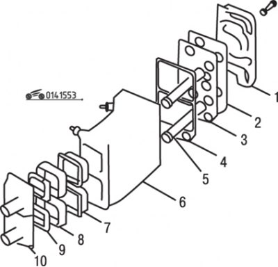
Pic. 15.53. Fastening elements of remote reed valves: 1 - back cover; 2, 4 - gaskets; 3 - distribution plate; 5 - guide tube; 6 - body; 7 - air filter; 8 - rubber insert; 9 - reed valve; 10 - front cover
For replacing remote reed valves (only for turbocharged engines) remove the valve body from the right shock absorber cup and lay it on a clean surface. Remove the four screws at the corners of the cover and remove the valve parts (pic. 15.53). During assembly, replace the gaskets and, if necessary, the rubber inserts.