
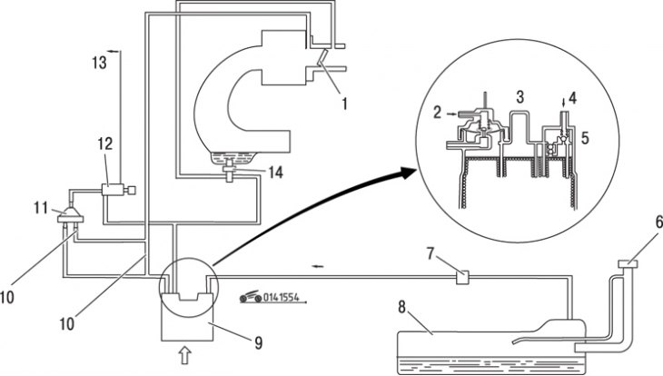
Pic. 15.54. Evaporative Emission System Schematic (EEC): 1 - throttle valve; 2 - from the water temperature valve; 3 - purge control valve No. 1; 4 - from the fuel tank; 5 - purge control valve No. 2; 6 - filler cap; 7 - three-way control valve; 8 – fuel tank; 9 - tank; 10 - throttle; 11 - purge control valve No. 3; 12 - three-way electromagnetic distributor; 13 - to the control unit; 14 - except for EU-AT
The fuel vapor recovery system ensures the absorption of gasoline vapors by the adsorber (activated carbon tank) when the engine is not running. When the engine is started, fuel vapors are sucked into the receiver and burned during engine operation (pic. 15.54).
Checking the evaporative emission system
To check the condition of the evaporative emission system, warm up the engine and set the idle speed. Disconnect the hose from the #1 purge control valve and connect a vacuum gauge to the disconnected hose. Bring the engine speed to 2500 min-1 and observe the readings of the vacuum gauge. The vacuum must be at least 150 mm Hg. Art. If the reading is different, check the water temperature valve. Attach hose to purge valve #1.
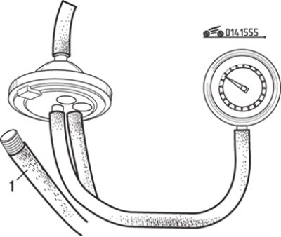
Pic. 15.55. Disconnecting the vacuum hose (1) from purge control valve #3
Disconnect the vacuum hose from the No. 3 purge control valve located above the ignition distributor and plug it with a suitable plug (pic. 15.55). Connect a vacuum gauge to the valve, start the engine and increase the crankshaft speed to 1500 min-1; vacuum gauge should show vacuum. If there is no vacuum, check the 3-way solenoid valve and purge control valve #3.
Disconnect the vacuum hose from the tank. Connect a vacuum pump to the evaporator hose and try to create a vacuum. If the three-way valve or evaporator tube is not clogged, vacuum cannot be generated. The appearance of a vacuum indicates a blockage in the evaporator tube or in the three-way control valve.
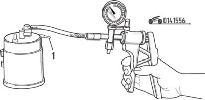
Pic. 15.56. Using a vacuum gauge and purging the channel (1) when checking purge control valve #1
To check control valve #1, purge the channel «A» (fig.15.56). Air must not pass through the valve. Attach a vacuum pump to purge valve #1 and apply a vacuum of 130 mmHg. Art. Air should now flow freely through the valve. If air does not pass, replace the canister canister.
To test the #2 purge control valve, disconnect the hose from the evaporator tube and purge the hose. Air must pass freely through the valve, otherwise replace the adsorber tank.
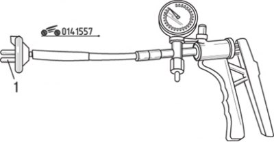
Pic. 15.57. Using a vacuum gauge and purging the channel (1) when checking purge control valve #3
To check the #3 purge control valve, remove it from the vehicle and connect the vacuum pump as shown in fig. 15.57. Purge channel 1 and verify that at a vacuum of less than 60 mmHg. Art. air is not passing through the valve. Create a vacuum of 75 mm Hg in the valve chamber. Art. In this case, air must pass freely through the valve. If both tests are negative, replace the valve.
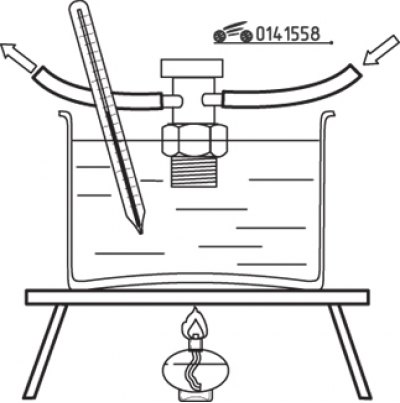
Pic. 15.58. Checking the water temperature valve by blowing it with air at a temperature of 50°C
To check the water temperature valve, unscrew it from the intake manifold and attach hoses to each of the fittings. Immerse the valve in water at 50°C and blow out the hose (pic. 15.58). Air must pass freely through the valve. Otherwise, replace the valve.
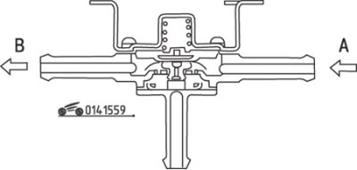
Pic. 15.59. Checking the three-way control valve: A, B, C - fitting
To check the three-way control valve, remove it from the vehicle. In accordance with fig. 15.59 Apply air to port A and check that air comes out of port B. Then close port B and check that air comes out of port C. Plug port B and connect a vacuum pump to port A. Create a vacuum and check that air is sucked into port C. If any of these tests fail, replace the 3-way control valve.
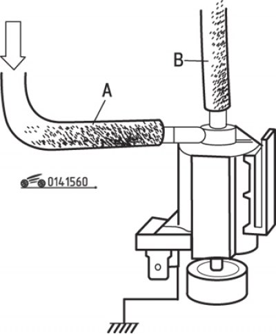
Pic. 15.60. Checking the three-way solenoid valve: A, B - fitting
To check the three-way solenoid distributor, remove it from the vehicle. Attach hoses to each of the valve fittings in accordance with fig. 15.60. Blow air into port A and check that air comes out of the air filter. Then apply battery voltage to the valve contacts - air should come out of port B. If the test results are negative, replace the valve.
Replacing elements
Two purge valves are built into the adsorber tank, so they cannot be replaced separately. To replace the #3 purge valve, disconnect the hoses one at a time and attach them to the new valve.
To remove the water temperature valve, cool the engine, then drain the coolant to a level below the valve. Disconnect the two vacuum hoses and remove the valve from the intake manifold. Wrap the threaded part of the valve with Teflon tape before installation. Check the integrity of the ends of the hoses. The presence of cracks or hardening may be the cause of leakage. Screw on the valve by hand, then tighten securely with a wrench. Put the hoses on the valve fittings and restore the coolant level.
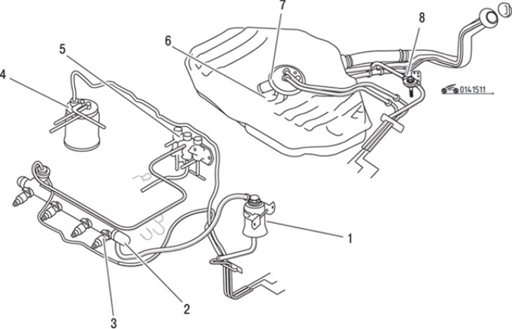
Pic. 15.11. Elements of the fuel supply system: 1 - fuel filter (on the high pressure line); 2 - fuel distribution line; 3 - nozzle; 4 - tank; 5 - control valve of the pressure regulator; 6 - fuel tank filter (on the suction side); 7 - fuel pump; 8 - three-way distribution valve
Three-way check valve installed next to the fuel tank (see fig. 15.11). For proper assembly, tape the labels, then loosen the clamps and disconnect the hoses from the valve. Turn out screws and remove the valve. Replace hoses if cracked or hardened. Installation is carried out in the reverse order of removal. Put the hoses on the appropriate fittings and secure with clamps.
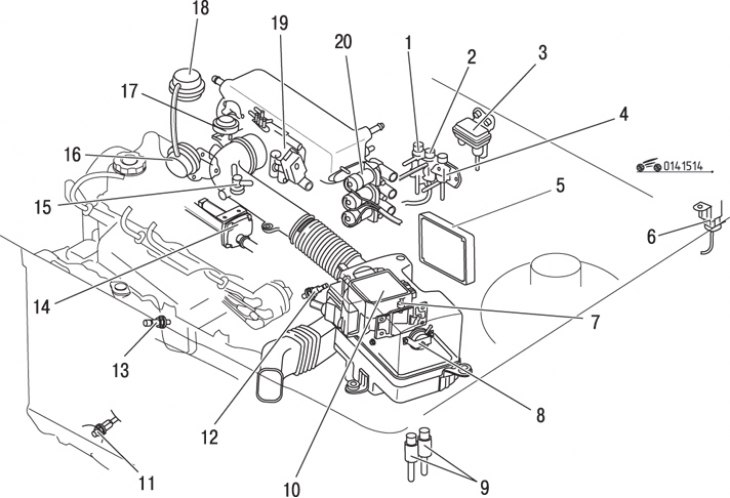
Pic. 15.14. Location of elements of the electronic engine control system without turbocharging: 1 - three-way electromagnetic distributor; 2 - control valve of the pressure regulator; 3 – atmospheric pressure sensor; 4 - three-way electromagnetic distributor; 5 - control unit; 6 - fuel pump relay; 7 - intake air temperature sensor; 8 - control air valve; 9 - main relay; 10 - air flow meter; 11 - temperature switch; 12 - analog coolant temperature sensor; 13 – oxygen concentration sensor; 14 - air valve; 15 - thermostat; 16 - control valve for exhaust gas recirculation; 17 - pneumatic shock absorber; 18 - recirculation valve with a smooth characteristic; 19 - throttle opening angle sensor; 20 - bypass solenoid valve
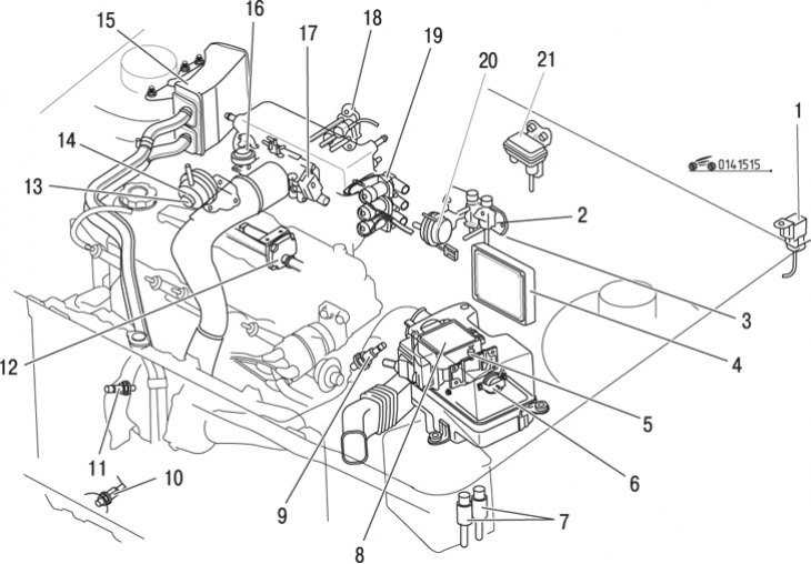
Pic. 15.15. The location of the elements of the electronic control system of the turbocharged engine: 1 - self-unblocking relay of the fuel pump; 2 - control valve of the pressure regulator; 3 - three-way electromagnetic distributor; 4 - control unit; 5 - intake air temperature sensor; 6 - control air valve; 7 - main relay; 8 - air flow meter; 9 - analog coolant temperature sensor; 10 – temperature switch; 11 – oxygen concentration sensor; 12 - air valve; 13 - control valve for exhaust gas recirculation; 14 - position sensor for exhaust gas recirculation; 15 - reed valve body; 16 - pneumatic shock absorber; 17 - throttle assembly; 18 - solenoid recirculation valve; 19 - bypass solenoid valve; 20 - pressure switch; 21 - atmospheric pressure sensor
The three-way solenoid valve is mounted on the wall of the engine compartment, in most cars it is located on the very left edge of the panel (see fig. 15.14, 15.15). To remove the valve, attach tags to the hoses with adhesive tape to re-install them when reassembling, then remove the hoses. Disconnect the connector, use a small screwdriver to remove the circlip and pull the valve out of the panel. Installation is carried out in the reverse order of removal.