
Checking the exhaust gas recirculation system
The location of the system elements is shown in fig. 15.14, 15.15.
Check the condition of the vacuum hoses. Bends, weakening of their tightness, twisting and tears are not allowed. On cars 1988–1991 release, check that the diaphragm under the recirculation valve moves easily, without jamming; to do this, insert your hand under the valve and press the diaphragm. Start the engine and check that the diaphragm moves up as the engine speed increases.
On cars 1986 and 1987. release, disconnect the vacuum hose from the recirculation valve and close it with a plug, the nature of the engine should not change. Otherwise, check the valve.
Connect a vacuum gauge to the disconnected hose (for turbocharged engines). There should be no vacuum at idle, the vacuum gauge should show vacuum at an engine speed of 2500 min-1. Otherwise, check the recirculation solenoid valve. Connect the hose.
On cars 1986 and 1987. exhaust with non-turbocharged engines, disconnect the hose from the recirculation smoothing valve and close it with a plug. Attach a piece of hose to the released fitting of the smoothing valve, bring the engine speed to 2500 min-1, blow into the hose and watch the vacuum gauge readings, which should increase. If the vacuum does not increase, check the smoothing valve. Attach hoses.
On vehicles equipped with turbocharged engines, connect a vacuum gauge between the recirculation solenoid valve and the recirculation control valve. Increase the engine speed and read the vacuum gauge. Then disconnect the hose from the recirculation valve and close it with a plug, the reading should be less than the previous one. Otherwise, check the recirculation position sensor and the recirculation solenoid valve.
With the vacuum hose plugged, disconnect the connector from the temperature switch on the radiator expansion tank. Bring the engine speed to 2500 min-1 - the vacuum gauge should not register a vacuum. Otherwise, check the recirculation solenoid valve.
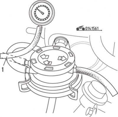
Pic. 15.61. Disconnecting the hose (1) and connecting a vacuum gauge instead to check the recirculation smoothing valve
On cars 1986 and 1987. exhaust with non-turbo engines, disconnect the hose from the recirculation smoothing valve and connect a vacuum gauge instead (pic. 15.61). Bring the engine speed up to 2500 min-1, while the vacuum gauge readings should be at least 150 mm Hg. Art. If the reading is different, check the three-way solenoid valve. Disconnect the connector from the temperature switch on the expansion tank - the vacuum gauge should not register a vacuum. Otherwise, check the three-way solenoid valve.
To check the recirculation control valve on both turbocharged and non-turbo engines, warm up the engine to normal operating temperature, then disconnect the hose from the smoothing valve and plug it; the nature of the engine should not change. Otherwise remove the valve and clean the channel of release of the fulfilled gases and draft of the valve.

Pic. 15.62. Exhaust Gas Recirculation Smoothing Valve Check: a - blowing direction
Connect a vacuum pump to the recirculation control valve and apply a vacuum of at least 75 mmHg. Art. The engine should start to run rough or stall. If it doesn't, replace the valve. To check the recirculation smoothing valve (only in non-turbocharged engines) it must be removed from the engine. Connect the vacuum pump to the fitting No. 3, close the fitting No. 1 with a plug and, with the pump running, blow into the exhaust gas fitting - the vacuum should not change (pic. 15.62). After depressurizing the exhaust port, the vacuum must not be maintained. If vacuum persists, replace smoothing valve.
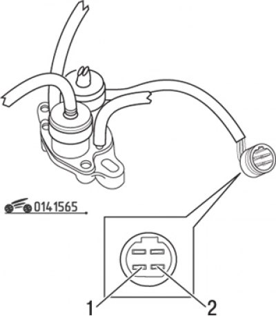
To test the recirculation position sensor (only in turbocharged engines) remove the rubber boot from the sensor connector without disconnecting the connector.
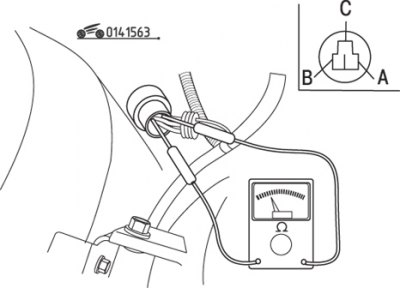
Pic. 15.63. Measurement of voltages on the pins of the position sensor connector
Disconnect the vacuum hose from the recirculation control valve and connect the vacuum pump. Turn the key in the ignition switch to position «ON» and measure the voltage at each pin of the connector (pic. 15.63). The measurement conditions are given in table. 15.15.
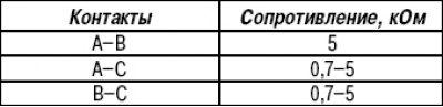
Table 15.15. Change in voltage at the pins of the position sensor connector depending on the vacuum
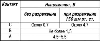
If the voltage at the contacts «A» And «IN» differs from the values given in table. 15.15, check the wires and hand over the control unit for testing to the service center. If the voltage on the contact is different «WITH», check the resistance of the sensor, then check the wires and hand over the control unit for verification to a service center.
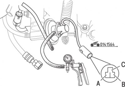
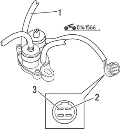
Pic. 15.64. Measurement of resistance between the pins of the position sensor connector
Disconnect the connector and measure the resistance between the pins of the position sensor (pic. 15.64). If any resistance differs from that given in Table. 15.16, replace recirculation control valve assembly (position sensor not supplied separately).
Table 15.16. Resistance between position sensor connector pins
Recirculation solenoid valve (only in turbocharged engines) consists of two valves - ventilation and vacuum. To check the vent valve, disconnect the hoses and blow through the vent duct - air should flow freely.
Pic. 15.65. The location of the connector pins that need to be energized from the battery when checking the ventilation solenoid valve: 1 – «weight»; 2 - positive voltage from the battery
Disconnect the connector and apply voltage from the storage battery to the connector pins in accordance with fig. 15.65. Blow through the ventilation duct again - air must not pass, otherwise replace the valve.
To check the vacuum valve, disconnect the hoses and blow through the vacuum channel - air should not pass.
Pic. 15.66. The location of the connector pins that need to be energized from the battery when checking the recirculation solenoid valve: 1 - vacuum hose; 2- «weight»; 3 - positive voltage from the battery
Disconnect the connector and apply voltage from the storage battery to the connector pins in accordance with fig. 15.66. Blow out the vacuum channel again - the air must pass freely, otherwise replace the valve.
Replacement of elements of the exhaust gas recirculation system
Remove the recirculation control valve only after the engine has completely cooled down. Mark and disconnect the vacuum hoses, unscrew the three bolts and remove the valve. Remove gasket residue from valve contact surfaces. Installation is carried out in the reverse order of removal.
To remove the smoothing recirculation valve, mark all hoses with tape to ensure they are properly connected. Release the spring clip and remove the valve. Installation is carried out in the reverse order of removal.
If the recirculation position sensor is defective, it must be replaced as an assembly, since the sensor is not sold separately.
To replace the recirculation solenoid valve, tape all the hoses to ensure they are properly connected and disconnect them. Turn away nuts and remove the electromagnetic valve from a wall of a motor compartment. Installation is carried out in the reverse order of removal.