


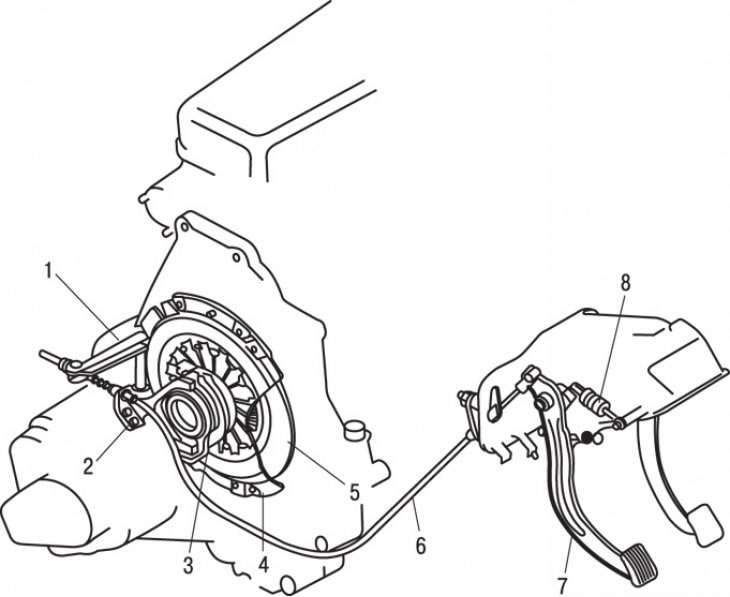
Figure 9.1. Location of clutch components on a vehicle: 1 – clutch release lever; 2 – clutch release fork; 3 – clutch release bearing; 4 – clutch housing assembly with pressure plate; 5 – driven clutch disc; 6 – clutch release cable; 7 – clutch pedal; 8 – spring
On vehicles equipped with a manual transmission, a dry single-plate diaphragm clutch is used (figure 9.1). The clutch is cable driven.
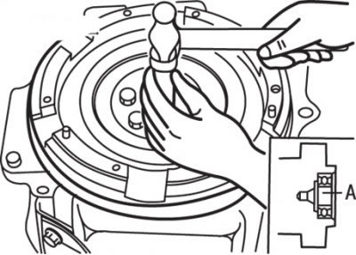
Figure 9.11. Using a hammer and drift to install a needle bearing: A=25–28 mm
Clearance between the needle bearing and the end surface of the crankshaft (distance A in Figure 9.11) is 2.5–2.8 mm.
Tightening torques, Nm
- Clutch release lever and fork mounting bolt - 11
- Bolts securing the pressure plate to the flywheel — 22–27
- Wheel drive shaft to hub mounting nut — 160–240
- Flywheel mounting bolts - 98-105
- Anti-roll bar mounting nut — 12–18
- Bolts for fastening the steering knuckle to the shock absorber - 95-119
- Steering knuckle to ball joint mounting bolts — 44–55
- Wheel nut - 90-120
Original material on the website mazbook.ru