


Contents: Clutch pedal installation height ⇓ Free play and height of the…⇓ Clutch master cylinder ⇓ Clutch slave cylinder ⇓ Removal air from the hydraulic…⇓
Some vehicles produced since 1986 are equipped with a hydraulic clutch. The hydraulic clutch system consists of a pedal, a master cylinder with a reservoir, a pipeline, a slave cylinder that actuates the clutch release fork, and a clutch release bearing.
First, checks should be carried out to determine the causes of malfunctions in the hydraulic clutch drive system. First, you need to check the level of the working fluid in the tank. If the level drops, add fluid and visually check for leaks throughout the entire system line. To check that the clutch is fully disengaged, measure the full stroke of the slave cylinder rod. When you press the clutch pedal, the rod should extend to its full length.
Clutch pedal installation height
Measure the distance from the body floor to the surface of the clutch pedal pad.
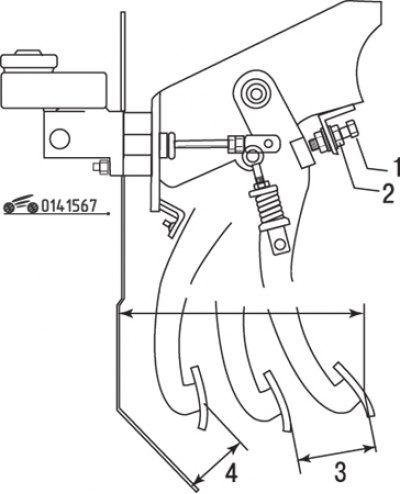
Figure 15.67. Adjusting the position of the clutch pedal: 1 – limiter bolt; 2 – lock nut; 3 – free travel of the clutch pedal; 4 – distance to the floor with the clutch fully disengaged
If the result does not match the required value, loosen the pedal travel limiter lock nut and rotate the limiter bolt (figure 15.67) until the pedal is set to the required position (on later production vehicles, the limiter bolt may be combined with the switch on the clutch pedal).
Tighten the lock nut.
Free play and height of the depressed clutch pedal
Press the pedal with your hand and measure the free play (the distance from the starting position to the appearance of noticeable resistance to the pedal stroke).
If the result is not as required, loosen the clutch master cylinder piston rod lock nut and rotate the piston rod until the required free play is obtained.
Check the height of the fully depressed clutch pedal (clutch release height).
Tighten the lock nut.
Clutch master cylinder
Removal
Disconnect the cable from the negative battery terminal.
On some vehicles it may be necessary to remove the relay tower.
Disconnect the hydraulic line from the clutch master cylinder. It is recommended to hold the tube with a spanner when unscrewing the fitting, which will prevent it from twisting together with the fitting. Place a container or rag underneath beforehand, as the working fluid may spill when disconnecting the tube.
Caution! Avoid contact with brake fluid on your vehicle's paintwork, as it will damage its shine.
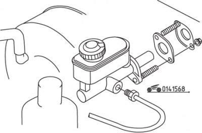
Figure 15.68. Clutch master cylinder fastening elements
Loosen the nuts securing the master cylinder to the engine compartment wall. One nut is located on the wall of the engine compartment, and the second is under the instrument panel on the brake pedal bracket (figure 15.68).
Carefully remove the cylinder from the rod and pull it out through the engine compartment wall.
Installation
Carefully insert the cylinder through the engine compartment wall and insert the piston rod. Tighten the nuts by hand.
Attach the hydraulic line to the clutch master cylinder by gently manipulating the cylinder to screw the fitting on the line into the threaded hole in the cylinder. Be careful not to damage the threads when screwing in the fitting.
Tighten the mounting nuts and the hydraulic drive tube fitting securely.
Fill the clutch reservoir with DOT-3 brake fluid and bleed the hydraulic system.
Connect the cable to the negative battery terminal and check the operation of the clutch before driving.
Clutch slave cylinder
Removal
Disconnect the cable from the negative battery terminal.
Raise the car and secure it on stands.
Disconnect the hydraulic line from the clutch slave cylinder. It is recommended to hold the tube with a spanner when unscrewing the fitting to prevent the tube and fitting from twisting. Place a container or rag underneath beforehand, as the working fluid may spill when disconnecting the tube.
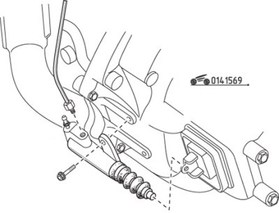
Figure 15.69. Clutch slave cylinder fastening elements
Loosen the clutch slave cylinder mounting bolts and remove it (figure 15.69).
(The original text can be found on: mazbook.ru)
Installation
Install the slave cylinder onto the clutch housing and make sure that the cylinder rod enters the recess of the clutch release fork, tighten the mounting bolts.
Attach the hydraulic line to the cylinder and tighten the fitting, being careful not to damage the threads.
Fill the clutch master cylinder reservoir with DOT-3 compliant brake fluid.
Remove air from the hydraulic drive.
Connect the cable to the negative battery terminal and check the operation of the clutch before driving.
Removal air from the hydraulic clutch drive (pumping)
Air must be removed when removing any component of the hydraulic drive system or when the fluid level drops to the point where air enters the clutch cylinder. The operation is similar to removing air from the brake system (bleeding).
Fill the clutch master cylinder reservoir with fresh DOT-3 compliant brake fluid.
Caution! When removing air, do not use liquid that has been used or has been stored in an open container for a long time.
To access the slave cylinder, raise the vehicle and support it on stands.
Remove the dust cap from the air bleed nipple and place a piece of plastic hose onto the nipple. Place the end of the hose in a clean container filled with brake fluid to a level of approximately 5 cm. The end of the hose should be immersed in the fluid.
Ask an assistant to press and hold the clutch pedal. Unscrew the air bleed nipple on the working cylinder to allow the liquid to drain into the container. While the liquid is flowing out, tighten the nipple. After this, ask the assistant to release the pedal.
Repeat this cycle until the air is completely removed from the system, as evidenced by the absence of bubbles in the fluid collection container and in the fluid flowing through the hose each time you press the pedal. Carefully monitor the fluid level in the feed tank. If the level drops too low, air may be drawn into the system, requiring re-bleeding.
Install the dust cap and lower the vehicle. Check the operation of the clutch.