
MazBook.ru
English Русский
Български
Беларускі
Український
Српски
Hrvatski
Română
Polski
Slovenský
Magyar
• Bookmark • Sitemap • Contacts •   
Cars Opel Cars Ford Cars Volkswagen Cars Audi Cars Kia Cars Renault Cars Peugeot


Familia Capella Mazda3 Mazda6 CX-? Others Articles
Capella 3 (1982-1992, petrol) Capella 3 and 4 (1982-1992) Capella 4 (1987-1992) Capella 5 (1991-1997) Capella 6 (1997-2005, petrol)

Clutch repair — removal, inspection and installation (Mazda Capella GC)

  • Home
  • Mazda Capella
  • Capella GC (1982-1992)
  • Transmission
  • Clutch
  • Clutch repair — removal, inspection and installation
0
Contents: Removal ⇓ Visual inspection ⇓ Installation ⇓

Removal


Remove the gearbox.

Mark the position of the pressure plate on the flywheel so that it can be returned to its original position during assembly.

Use a special alignment tool or a screwdriver handle to support the clutch disc while removing the pressure plate.

Using a special tool or a screwdriver, lock the flywheel ring gear teeth to prevent it from turning.

Gradually loosen the clutch assembly mounting bolts diagonally, turning each bolt half a turn until the spring force is released and the bolts can be removed by hand.
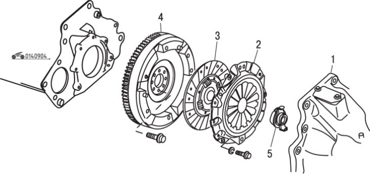
Figure 9.4. Location of clutch elements: 1 – gearbox; 2 – clutch housing with pressure plate; 3 –…

Figure 9.4. Location of clutch elements: 1 – gearbox; 2 – clutch housing with pressure plate; 3 – driven clutch disc; 4 – flywheel; 5 – clutch release bearing


Remove the pressure plate, supporting the driven plate so that it does not fall out (figure 9.4).

Handle the clutch disc carefully, taking care not to touch the lining surfaces, and move it to the side.
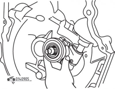
Figure 9.5. Removing the clutch release bearing

Figure 9.5. Removing the clutch release bearing


Disconnect the return spring from the clutch release fork hook, rotate the release lever and remove the clutch release bearing (figure 9.5).

Remove the clutch release fork mounting bolt and remove the fork and lever assembly.

Visual inspection


Use an electric vacuum cleaner or a clean cloth to clean the clutch cover from dust. Do not use compressed air, as inhaling dust containing asbestos is harmful to health.

Inspect the pressure plate for signs of damage and wear of the diaphragm spring, scratches, scoring or discoloration (indicates overheating) surface, make sure there are no signs of damage or deformation of the casing. Minor defects in the friction surface can be removed with fine-grained sandpaper, but the pressure plate should be replaced with a new one if there is any doubt about its condition.

Inspect the flywheel surface for uneven contact with the clutch driven disc, which indicates improper installation or damage to the clutch diaphragm spring. Inspect the surface for burrs, grooves, cracks or other signs of wear. If necessary, remove the flywheel and machine it to restore the surface. The flywheel surface can be polished using fine-grained sandpaper.
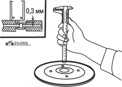
Figure 9.6. Measuring wear of the friction linings of the driven clutch disc

Figure 9.6. Measuring wear of the friction linings of the driven clutch disc


Inspect the clutch driven disc friction linings for contamination with oil, grease or any other substance and replace the driven disc if necessary. Check the driven disc for wear by measuring the distance from the rivet head to the lining surface. Replace the disc if the wear of the friction linings has reached the limit shown in the figure 9.6.

Inspect the driven clutch disc for deformation, wear, loose rivets and springs, and damage to the hub splines. Temporarily install the driven clutch disc onto the transmission input shaft and check for smooth fit, nicks, and wear on the splines. If there is any doubt about the condition of the clutch disc, replace it.
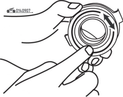
Figure 9.7. Checking the smooth rotation of the clutch release bearing
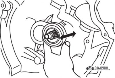
Figure 9.7. Checking the smooth rotation of the clutch release bearing


Figure 9.8. Checking the sliding of the clutch release bearing on the input shaft of the gearbox

Figure 9.8. Checking the sliding of the clutch release bearing on the input shaft of the gearbox


Check the clutch release bearing for wear and ensure that it rotates smoothly, without any extraneous noise, and slides easily on the transmission input shaft (figure 9.7, 9.8). Unless the vehicle has very low mileage, it is recommended to replace the bearing with a new one every time the clutch is removed.

Inspect the clutch housing, release lever and return spring for wear, cracks, deformation, damage and metal fatigue, replacing as necessary.
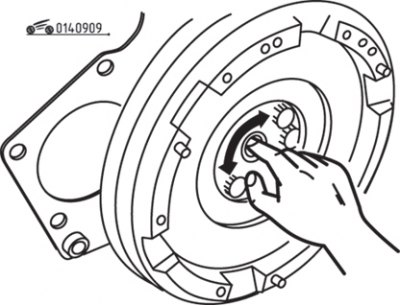
Figure 9.9. Checking the smooth rotation of the needle bearing at the end of the crankshaft
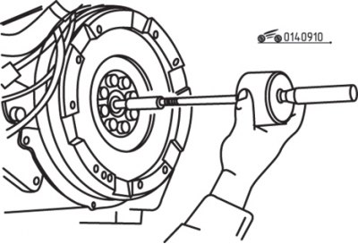
Figure 9.9. Checking the smooth rotation of the needle bearing at the end of the crankshaft


Figure 9.10. Using an inertial puller to remove a needle bearing

Figure 9.10. Using an inertial puller to remove a needle bearing


Check the needle bearing at the end of the crankshaft to make sure it rotates easily and smoothly with just your finger (figure 9.9). If necessary, replace the bearing by removing it with an inertial puller and installing a new one into the crankshaft hole using a mandrel or a piece of tube of the appropriate diameter and a hammer (figure 9.10). Before installation, lubricate the new bearing and during installation, follow the reference distance shown in the figure 9.11.


Installation


When installing a new driven disc or clutch pressure plate, remove the anti-corrosion protection from them.

When installing the driven disk, make sure that not even a small amount of oil gets on its friction linings. Therefore, before installation, wipe the mating surface of the flywheel and the surface of the pressure plate with a clean rag, install the driven disk with clean hands.

Before installation, lubricate the clutch release bearing, input shaft splines, and clutch disc splines with a Moly-based lubricant. Be careful not to allow lubricant to come into contact with the friction surfaces of the clutch disc, flywheel, and pressure plate.

Hold the clutch driven disc with a special centering tool or a round rod, install the clutch assembly, aligning the holes in the clutch housing with the flywheel guide pins. When reinstalling a previously removed clutch pressure plate, check that the marks made before removal are aligned.

Tighten the clutch mounting bolts so that the driven clutch disc is pressed down, but at the same time can still move sideways.

Using a special drift or an old gearbox input shaft, center the clutch disc relative to the flywheel.

Caution! If the clutch disc is not centered, it will be impossible to install the gearbox.


After centering the driven disc, gradually tighten the clutch housing mounting bolts diagonally to the required torque.

Remove the mandrel from the driven disk.

Install the clutch release lever, release fork, spring and release bearing.
This article is available at: russian, bulgarian, belarusian, ukrainian, serbian, croatian, romanian, polish, slovak, hungarian
This text was checked by: Georgy Afanasyev
Share with friends on social networks:

Previous
Capella 3 and 4 » Clutch
Next

Clutch cable — removal and installation
Clutch pedal — removal and installation
Checking the clutch operation
General information about clutch
Clutch components for models produced since 1986
More articles on repairing other Mazda models
Repair of cylinder head of engines B3, B5, B6 Mazda Familia 5 (1985-1989)
General information about the clutch Mazda3 BK (2003-2009)
General information about the clutch Mazda6 GG (2002-2008)
Temporary tyre repair kit (optional) Mazda CX-5KE (2012-2017)
Clutch — design description Mazda 121 (3) (1996-2003)
Link in different formats to this article
Comments and feedback from visitors
No comments yet


How much will 31 + 28 ?


Capella 6 (1997-2005, petrol) 
  • General information
  • Introduction to guide
  • User manual
  • Troubleshooting
  • Maintenance
  • Power unit
  • 4-cylinder engines
  • 6-cylinder engines
  • Engine overhaul
  • Cooling and ventilation
  • Power and exhaust systems
  • Engine electrics
  • Control system
  • Transmission
  • Mechanical gearbox
  • Automatic gearbox
  • Clutch and drive shafts
  • Chassis
  • Brake system
  • Car suspension
  • Steering
  • Body
  • Exterior (external elements)
  • Interior (internal elements)
  • Doors, windows and locks
  • Electrical equipment
  • Equipment and devices
  • Electrical circuits
Capella 5 (1991-1997) 
  • General information
  • User manual
  • Maintenance
  • Helpful hints
  • Power unit
  • Petrol engines 1.6 and 1.8
  • Petrol engines 2.0
  • 2.5 petrol engines
  • Overhaul engines 1.6 and 1.8
  • Overhaul engines 2.0 and 2.5
  • Diesel engine 2.0
  • Engine electrics
  • Cooling system
  • Air conditioner
  • Carburetor Nikki 30/34
  • Power system (1.6 and 1.8)
  • Power system (2.0 and 2.5)
  • Control system
  • Transmission
  • Mechanical gearbox
  • Automatic gearbox
  • Clutch and axles
  • Chassis
  • Brake system
  • Suspension and wheels
  • Steering
  • Body
  • Exterior (external elements)
  • Interior (internal elements)
  • Doors and windows
  • Electrical equipment
  • Equipment and devices
  • Electrical circuits
Capella 4 (1987-1992) 
  • General information
  • Introduction to manual
  • Vehicle specifications
  • Power unit
  • Engine repair
  • Lubrication system
  • Cooling system
  • Fuel system (carburetor)
  • Fuel injection (FE)
  • Fuel injection (DOHC)
  • Fuel system (diesel)
  • Ignition system
  • Transmission
  • Clutch
  • Gearbox
  • Drive shafts
  • Chassis
  • Front suspension
  • Rear suspension
  • Steering system
  • Brake system
  • Electrical equipment
  • Equipment and devices
  • Electrical circuits
Capella 3 and 4 (1982-1992) 
  • General information
  • User manual
  • Maintenance
  • Power unit
  • Gasoline engine
  • Engine overhaul (gasoline)
  • Diesel engine
  • Cooling and heating
  • Supply system
  • Ignition system
  • Emission reduction
  • Transmission
  • Clutch
  • Mechanical gearbox
  • Automatic gearbox
  • Drive shafts
  • Chassis
  • Brake system
  • Suspension and wheels
  • Steering
  • Body
  • Exterior (external elements)
  • Interior (internal elements)
  • Electrical equipment
  • Equipment and devices
  • Power devices
  • Electrical circuits
Capella 3 (1982-1992, petrol) 
  • General information
  • User manual
  • Maintenance
  • Troubleshooting
  • Late models
  • Power unit
  • Engine in car
  • Engine overhaul
  • Cooling and heating system
  • Fuel and exhaust system
  • Engine electrical system
  • Emission control system
  • Transmission
  • Mechanical gearbox
  • Automatic gearbox
  • Clutch and drive shafts
  • Chassis
  • Brake system
  • Suspension and wheels
  • Steering
  • Body
  • Exterior (external elements)
  • Interior (internal elements)
  • Electrical equipment
  • Equipment and devices
  • Lighting and lamps
  • Electrical circuits
MazBook.ru © 2018–2026 · Mobile version · Articles and news · Sitemap: EN BG BY UA RS HR RO PL SK HU · Feedback · Site search · Add to bookmarks Familia 5 (BF) · Familia 6 (BG) · Capella 3 (GC) · Capella 3 and 4 (GC) · Capella 4 (GD) · Capella 5 (GE) · Capella 6 (GF) · Mazda3 BK · Mazda6 GG · CX-5KE · Mazda 121 (3) · Mazda BT-50 (1) ·
By continuing to use the site, you agree to the use of cookies 🔐