
MazBook.ru
English Русский
Български
Беларускі
Український
Српски
Hrvatski
Română
Polski
Slovenský
Magyar
• Bookmark • Sitemap • Contacts •   
Cars Opel Cars Ford Cars Volkswagen Cars Audi Cars Kia Cars Renault Cars Peugeot


Familia Capella Mazda3 Mazda6 CX-? Others Articles
Capella 3 (1982-1992, petrol) Capella 3 and 4 (1982-1992) Capella 4 (1987-1992) Capella 5 (1991-1997) Capella 6 (1997-2005, petrol)

Transverse suspension arm (Mazda Capella GD)

  • Home
  • Mazda Capella
  • Capella GD (1987-1992)
  • Chassis
  • Front suspension
  • Transverse suspension arm
0
Contents: 14.3.1. Removal ⇓ 14.3.2. Repair of the transverse…⇓ 14.3.3. Installation ⇓

14.3.1. Removal


The wishbone can be easily removed as there is no need to remove the shock absorber strut from the vehicle. Figure 190 shows the suspension arm and anti-roll bar components and work should be carried out using this figure.
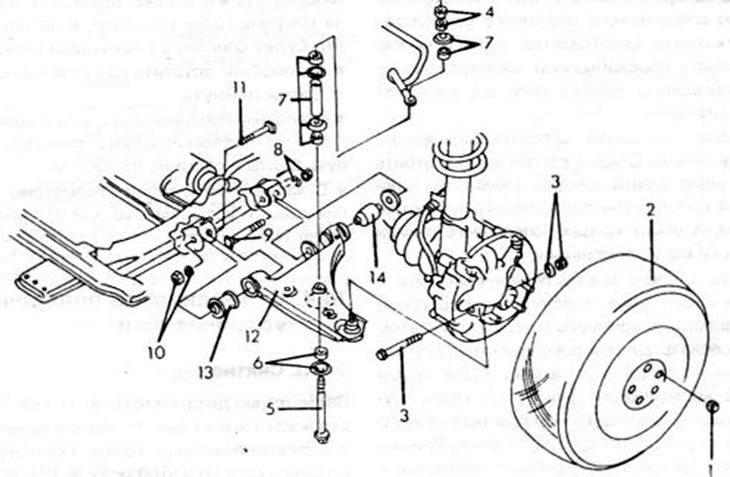
Figure 190. Details of removal and installation of the lower control arm: 1. Wheel nut, 90-120 Nm;…

Figure 190. Details of removal and installation of the lower control arm: 1. Wheel nut, 90-120 Nm; 2. Front wheel; 3. Bolt/nut, 44-56 Nm; 4. Nuts, 16-23 Nm; 5. Connecting bolt, stabilizer; 6. Washer and bushing; 7. Washers, bushings, sleeves; 8. Nut, 95-130 Nm; 9. Suspension control arm bolt; 10. Nut, 95-130 Nm; 11. Suspension control arm bolt; 12. Suspension wishbone; 13. Front bearing shell; 14. Rear bearing shell

  • Loosen the wheel mounting nut.
  • Raise the front of the car and lift the wheels.
  • On the underside of the steering knuckle, loosen the bolts and nuts of the ball-head mounts and knock out the bolts (figure 191, top).
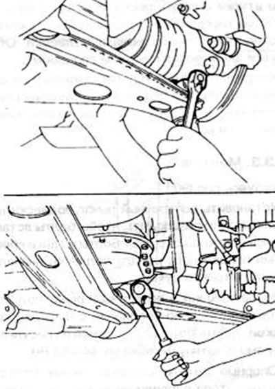
Figure 191. Removing the suspension ball joint from the steering knuckle (top) and releasing the…

Figure 191. Removing the suspension ball joint from the steering knuckle (top) and releasing the suspension wishbone (visu).


  • Remove both nuts from the top of the anti-roll bar connecting arms and remove the washers and rubber bushings. Pull the long bolts down and remove the remaining parts.
  • Press the suspension wishbone down and separate it from the steering knuckle.
  • Using the drawing 190, loosen the bolts and nuts (9) and (11) of the transverse suspension arm on the body. They are located in the location shown in the picture 191 (bottom). Pay attention to the direction the bolt head points.
  • Remove the wishbone.

14.3.2. Repair of the transverse suspension arm


  • The wishbone ball joint cannot be replaced.
  • If it becomes loose, the entire wishbone needs to be replaced. The ball joint can only be checked for wear using a special clamping device and a spring dynamometer, but a loose ball joint can be recognized by excessive play when it is pushed in or pulled out.
  • The ball joint dust cap can be replaced. The old cap can be knocked off with a chisel, and the new one is driven in using a piece of pipe of a suitable diameter. The bushings at both ends of the wishbone are replaceable.
  • To do this, you need to clamp the wishbone in a vice and carefully cut the outer side of the bushing with a saw. The bushings are then pressed out. To press it out, place a piece of pipe of the same outside diameter on the bushing between the jaws of the vice, and a piece of pipe of a larger size against the wishbone on the other side. When the vice is clamped, the bushings are pressed out and fall inside the larger piece of pipe. Lubricate the new bushings with soap and press them between the jaws of a vice until the flange is positioned against the wishbone. Both bushings are replaced in a similar manner.
  • Check the suspension arm for visible defects. If in doubt (for example, after an accident), the suspension arm needs to be checked at a Mazda workshop.


14.3.3. Installation


Using the drawing 190:
  • Install the wishbone onto the chassis. When doing this, make sure that the bolts are inserted from the correct side. At first, tighten the suspension arm mounting bolts and nuts only by hand.
  • After the ball head mount has been inserted into the wishbone, drive in the bolts from the side shown in the illustrations and tighten the nuts to 44-85 Nm.
  • Support parts of the anti-roll bar connecting bolts (rubber bushings, washers) put on as shown in the figure, screw on the nuts and tighten as described in the next chapter.
  • Lower the car onto its wheels and shake it several times.
  • Suspension control arm mount (on the suspension crossmember) can be fixed. Tighten the bolts and nuts to 95-30 Nm.
  • Finally, measure the geometry of the front wheels and install them. as described in chapter 14.5.
This article is available at: russian, bulgarian, belarusian, ukrainian, serbian, croatian, romanian, polish, slovak, hungarian
This text was checked by: Georgy Afanasyev
Share with friends on social networks:

Previous
Capella 4 » Front suspension
Next

Front wheel hubs
Shock absorber struts
Front wheel suspension
Anti-roll bar
Installing the front wheels
More articles on repairing other Mazda models
Removal and installation transverse suspension arms Mazda Familia 5 (1985-1989)
Rear suspension stabilization Mazda3 BK (2003-2009)
Rear suspension stabilization Mazda6 GG (2002-2008)
Removal/installing the front suspension strut Mazda CX-5KE (2012-2017)
Front suspension — design description Mazda 121 (3) (1996-2003)
Link in different formats to this article
Comments and feedback from visitors
No comments yet


How much will 14 + 49 ?


Capella 6 (1997-2005, petrol) 
  • General information
  • Introduction to guide
  • User manual
  • Troubleshooting
  • Maintenance
  • Power unit
  • 4-cylinder engines
  • 6-cylinder engines
  • Engine overhaul
  • Cooling and ventilation
  • Power and exhaust systems
  • Engine electrics
  • Control system
  • Transmission
  • Mechanical gearbox
  • Automatic gearbox
  • Clutch and drive shafts
  • Chassis
  • Brake system
  • Car suspension
  • Steering
  • Body
  • Exterior (external elements)
  • Interior (internal elements)
  • Doors, windows and locks
  • Electrical equipment
  • Equipment and devices
  • Electrical circuits
Capella 5 (1991-1997) 
  • General information
  • User manual
  • Maintenance
  • Helpful hints
  • Power unit
  • Petrol engines 1.6 and 1.8
  • Petrol engines 2.0
  • 2.5 petrol engines
  • Overhaul engines 1.6 and 1.8
  • Overhaul engines 2.0 and 2.5
  • Diesel engine 2.0
  • Engine electrics
  • Cooling system
  • Air conditioner
  • Carburetor Nikki 30/34
  • Power system (1.6 and 1.8)
  • Power system (2.0 and 2.5)
  • Control system
  • Transmission
  • Mechanical gearbox
  • Automatic gearbox
  • Clutch and axles
  • Chassis
  • Brake system
  • Suspension and wheels
  • Steering
  • Body
  • Exterior (external elements)
  • Interior (internal elements)
  • Doors and windows
  • Electrical equipment
  • Equipment and devices
  • Electrical circuits
Capella 4 (1987-1992) 
  • General information
  • Introduction to manual
  • Vehicle specifications
  • Power unit
  • Engine repair
  • Lubrication system
  • Cooling system
  • Fuel system (carburetor)
  • Fuel injection (FE)
  • Fuel injection (DOHC)
  • Fuel system (diesel)
  • Ignition system
  • Transmission
  • Clutch
  • Gearbox
  • Drive shafts
  • Chassis
  • Front suspension
  • Rear suspension
  • Steering system
  • Brake system
  • Electrical equipment
  • Equipment and devices
  • Electrical circuits
Capella 3 and 4 (1982-1992) 
  • General information
  • User manual
  • Maintenance
  • Power unit
  • Gasoline engine
  • Engine overhaul (gasoline)
  • Diesel engine
  • Cooling and heating
  • Supply system
  • Ignition system
  • Emission reduction
  • Transmission
  • Clutch
  • Mechanical gearbox
  • Automatic gearbox
  • Drive shafts
  • Chassis
  • Brake system
  • Suspension and wheels
  • Steering
  • Body
  • Exterior (external elements)
  • Interior (internal elements)
  • Electrical equipment
  • Equipment and devices
  • Power devices
  • Electrical circuits
Capella 3 (1982-1992, petrol) 
  • General information
  • User manual
  • Maintenance
  • Troubleshooting
  • Late models
  • Power unit
  • Engine in car
  • Engine overhaul
  • Cooling and heating system
  • Fuel and exhaust system
  • Engine electrical system
  • Emission control system
  • Transmission
  • Mechanical gearbox
  • Automatic gearbox
  • Clutch and drive shafts
  • Chassis
  • Brake system
  • Suspension and wheels
  • Steering
  • Body
  • Exterior (external elements)
  • Interior (internal elements)
  • Electrical equipment
  • Equipment and devices
  • Lighting and lamps
  • Electrical circuits
MazBook.ru © 2018–2026 · Mobile version · Articles and news · Sitemap: EN BG BY UA RS HR RO PL SK HU · Feedback · Site search · Add to bookmarks Familia 5 (BF) · Familia 6 (BG) · Capella 3 (GC) · Capella 3 and 4 (GC) · Capella 4 (GD) · Capella 5 (GE) · Capella 6 (GF) · Mazda3 BK · Mazda6 GG · CX-5KE · Mazda 121 (3) · Mazda BT-50 (1) ·
By continuing to use the site, you agree to the use of cookies 🔐