MazBook.ru
English Русский
Български
Беларускі
Український
Српски
Hrvatski
Română
Polski
Slovenský
Magyar
• Bookmark • Sitemap • Contacts •   
Cars Opel Cars Ford Cars Volkswagen Cars Audi Cars Kia Cars Renault Cars Peugeot


Familia Capella Mazda3 Mazda6 CX-? Others Articles
Capella 3 (1982-1992, petrol) Capella 3 and 4 (1982-1992) Capella 4 (1987-1992) Capella 5 (1991-1997) Capella 6 (1997-2005, petrol)

Installing the front wheels (Mazda Capella GD)

  • Home
  • Mazda Capella
  • Capella GD (1987-1992)
  • Chassis
  • Front suspension
  • Installing the front wheels
0
Contents: 14.5.1. Setting the camber and…⇓ 14.5.2. Camber adjustment ⇓ 14.5.3. Setting the steering angle…⇓
When checking the front wheel alignment, the vehicle must be parked on a flat surface and the tires must be inflated to the appropriate air pressure. Before measuring wheel alignment, it is important that the steering and wheel suspension are mounted as specified and have no play at all. The rims should not have any runout.

14.5.1. Setting the camber and kingpin inclination


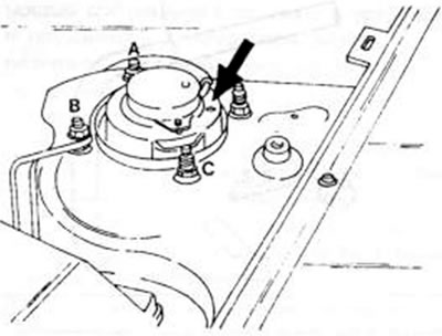
The camber and caster can be adjusted up to 27', while the upper shock absorber mount position can be changed. Changing the camber angle will damage the kingpin angle. During manufacturing, the shock absorber support is installed so that it corresponds to the prescribed value and must be marked before removal.

If the specified value is exceeded when measured in the usual way, it can in most cases be assumed that the front wheel suspension parts are warped and must be replaced accordingly; this happened because work was done on the front wheel suspension, which changed the value.

The camber cannot be more than 0° 17' with a tolerance of ±45'; kingpin inclination - 1° 17' with a tolerance of ±45.

When setting the camber and kingpin angle, the car must be brought into working condition, i.e. into the position as when driving. In addition, the fuel tank needs to be filled. When installing, proceed as follows:
  • Open the engine hood and unscrew the four nuts of the upper shock absorber mount from the casing in the engine compartment.
  • Place the front of the car on jack stands and unscrew the front wheels.
  • Press the shock absorber down until the studs are clear of the housing to move the alignment mark to a different location.


Designation (Fig. 196)Camber angleKingpin angle
A27'0°
IN+27'+28'
WITH0°+28'


Figure 196. Position of the alignment mark of the upper shock absorber strut support and three…

Figure 196. Position of the alignment mark of the upper shock absorber strut support and three bridges A, B and C, to which the alignment mark can be moved by repositioning the shock absorber strut support

  • Reconnect the shock absorber strut to the studs and tighten it in the new position with a tightening torque of 46–63 Nm.
  • Check the camber and kingpin angle again.

14.5.2. Camber adjustment


The camber is adjusted after loosening the lock nuts of the transverse steering point and lengthening or shortening the rod. Since the tie rod ends do not require relocation, they can remain connected to the steering knuckle arms. The tie rod arms should definitely be adjusted to the same length. The base length of the transverse steering rod on both sides must be brought to the same value, i.e. if one lever is changed, it must be brought to the previous length.

When measuring camber, proceed as follows:
  • Set the front wheels straight.
  • Set the correct toe-in of the front wheels on the rim flanges or in the middle of the wheels as shown in the figure 197. and set the scale to zero. Mark the convergence location with chalk.
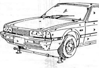
Figure 197. Convergence control.

Figure 197. Convergence control.


  • Remove the toe-in adjustment and move the vehicle forward half a wheel turn until the chalk mark at the hub height is on the rear side of the wheel.
  • With the toe still set to zero, now place it behind the wheels and adjust the probe. Read the result indicated on the scale.
  • If the dimension on the rear side is larger than on the front, then there is camber, and if the dimension is smaller, then there is kingpin tilt. The best setting is 3mm camber, but no adjustment is needed if the dimension is within plus or minus 3.0mm of the previously mentioned value. If the toe-in adjustment is necessary, it should be adjusted by 3 mm with a tolerance of +3 or -3 mm. When adjusting, proceed as follows:
  • Squeeze both ends of the clamp on the inside of the steering column cuffs and pull out the clamp.
  • Loosen the locknuts of both tie rods.
  • Adjust the tie rods on both sides with a wrench in the location shown in Figure 198. Both tie rods have right-hand threads, but you need to turn the right rod forward and the left rod back to achieve wheel camber. To limit the camber, you need to proceed in reverse order.

Based on website data (mazbook.ru)
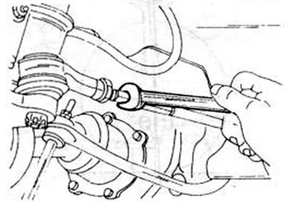
Figure 198. Adjusting the transverse steering rod to set the toe-in.

Figure 198. Adjusting the transverse steering rod to set the toe-in.


  • Check the alignment again, and if it's correct, tighten both locknuts to a torque of 70-100 Nm. Hold the tie rod ends with pliers.
  • Place the steering cuffs on the steering rack, squeeze both metal clamps and insert them into the grooves of the cuffs.


14.5.3. Setting the steering angle of the steering wheels


To accurately set the steering angle of the steering wheels, the front wheels are mounted on rotating discs.

The rotation angle can be taken from the table of parameters and installation dimensions. If necessary, check the length of the tie rods. Set the rods to the same length and check the rotation angle. Finally, check the wheel alignment and adjust if necessary.
This article is available at: russian, bulgarian, belarusian, ukrainian, serbian, croatian, romanian, polish, slovak, hungarian
This text was checked by: Georgy Afanasyev
Share with friends on social networks:

Previous
Capella 4 » Front suspension
Next

Anti-roll bar
Transverse suspension arm
Front wheel hubs
Shock absorber struts
Front wheel suspension
More articles on repairing other Mazda models
Installing the front wheel drive shafts Mazda Familia 5 (1985-1989)
Installing the front engine cover Mazda3 BK (2003-2009)
Installing the front engine cover Mazda6 GG (2002-2008)
Removal/installing the front suspension strut Mazda CX-5KE (2012-2017)
Ford KA: Removing and installing the front bumper and radiator grille Mazda 121 (3) (1996-2003)
Link in different formats to this article
Comments and feedback from visitors
No comments yet


How much will 27 + 46 ?


Capella 6 (1997-2005, petrol) 
  • General information
  • Introduction to guide
  • User manual
  • Troubleshooting
  • Maintenance
  • Power unit
  • 4-cylinder engines
  • 6-cylinder engines
  • Engine overhaul
  • Cooling and ventilation
  • Power and exhaust systems
  • Engine electrics
  • Control system
  • Transmission
  • Mechanical gearbox
  • Automatic gearbox
  • Clutch and drive shafts
  • Chassis
  • Brake system
  • Car suspension
  • Steering
  • Body
  • Exterior (external elements)
  • Interior (internal elements)
  • Doors, windows and locks
  • Electrical equipment
  • Equipment and devices
  • Electrical circuits
Capella 5 (1991-1997) 
  • General information
  • User manual
  • Maintenance
  • Helpful hints
  • Power unit
  • Petrol engines 1.6 and 1.8
  • Petrol engines 2.0
  • 2.5 petrol engines
  • Overhaul engines 1.6 and 1.8
  • Overhaul engines 2.0 and 2.5
  • Diesel engine 2.0
  • Engine electrics
  • Cooling system
  • Air conditioner
  • Carburetor Nikki 30/34
  • Power system (1.6 and 1.8)
  • Power system (2.0 and 2.5)
  • Control system
  • Transmission
  • Mechanical gearbox
  • Automatic gearbox
  • Clutch and axles
  • Chassis
  • Brake system
  • Suspension and wheels
  • Steering
  • Body
  • Exterior (external elements)
  • Interior (internal elements)
  • Doors and windows
  • Electrical equipment
  • Equipment and devices
  • Electrical circuits
Capella 4 (1987-1992) 
  • General information
  • Introduction to manual
  • Vehicle specifications
  • Power unit
  • Engine repair
  • Lubrication system
  • Cooling system
  • Fuel system (carburetor)
  • Fuel injection (FE)
  • Fuel injection (DOHC)
  • Fuel system (diesel)
  • Ignition system
  • Transmission
  • Clutch
  • Gearbox
  • Drive shafts
  • Chassis
  • Front suspension
  • Rear suspension
  • Steering system
  • Brake system
  • Electrical equipment
  • Equipment and devices
  • Electrical circuits
Capella 3 and 4 (1982-1992) 
  • General information
  • User manual
  • Maintenance
  • Power unit
  • Gasoline engine
  • Engine overhaul (gasoline)
  • Diesel engine
  • Cooling and heating
  • Supply system
  • Ignition system
  • Emission reduction
  • Transmission
  • Clutch
  • Mechanical gearbox
  • Automatic gearbox
  • Drive shafts
  • Chassis
  • Brake system
  • Suspension and wheels
  • Steering
  • Body
  • Exterior (external elements)
  • Interior (internal elements)
  • Electrical equipment
  • Equipment and devices
  • Power devices
  • Electrical circuits
Capella 3 (1982-1992, petrol) 
  • General information
  • User manual
  • Maintenance
  • Troubleshooting
  • Late models
  • Power unit
  • Engine in car
  • Engine overhaul
  • Cooling and heating system
  • Fuel and exhaust system
  • Engine electrical system
  • Emission control system
  • Transmission
  • Mechanical gearbox
  • Automatic gearbox
  • Clutch and drive shafts
  • Chassis
  • Brake system
  • Suspension and wheels
  • Steering
  • Body
  • Exterior (external elements)
  • Interior (internal elements)
  • Electrical equipment
  • Equipment and devices
  • Lighting and lamps
  • Electrical circuits
MazBook.ru © 2018–2026 · Mobile version · Articles and news · Sitemap: EN BG BY UA RS HR RO PL SK HU · Feedback · Site search · Add to bookmarks Familia 5 (BF) · Familia 6 (BG) · Capella 3 (GC) · Capella 3 and 4 (GC) · Capella 4 (GD) · Capella 5 (GE) · Capella 6 (GF) · Mazda3 BK · Mazda6 GG · CX-5KE · Mazda 121 (3) · Mazda BT-50 (1) ·
By continuing to use the site, you agree to the use of cookies 🔐