


Contents: 14.4.1. Withdrawal ⇓ 14.4.2. Installation ⇓
14.4.1. Withdrawal
- The fastening of the parts is shown in figure 190. The figure shows the design of a car with two-wheel steering. The following description concerns this model. With four-wheel steering installed, the entire front subframe must be released from the body to access the individual mountings.
- Loosen the wheel nuts, raise the vehicle's lug nuts and remove the wheels.
- Unscrew the mudguard.
- Remove both nuts of the stabilizer connecting bolts from the upper side of the wishbone and remove the released parts.
- With the four-wheel steering installed, release the controls shown in the figure 192 bolts of both side members.
- Unscrew the metal earring of the stabilizer support on the front side.
- Remove the stabilizer.
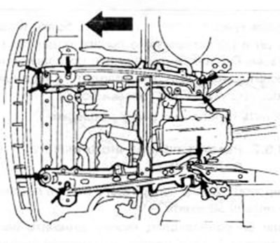
Figure 192. With four-wheel steering installed, loosen the trailing arm bolts shown by the arrows
14.4.2. Installation
The anti-roll bar rubber bushings are replaceable. Check the stabilizer for distortion before reinstalling it. The stabilizer is installed in the reverse order of removal, observing the following points:
- Temporarily install both mounting brackets, but leave them loose enough to allow the rubber bushings to be moved.
- Install both connecting arms on the suspension wishbone. Tighten the first nut with your hand on the top side of the lever.
- Install both rubber bushings according to Figure 193. The edge of each bushing must be installed on the same axis as the white line of the stabilizer arm. If the stabilizer is dirty, it must of course be cleaned first so that the lines can be seen. The bushings need to be turned so that the splined holes point towards the rear of the vehicle.
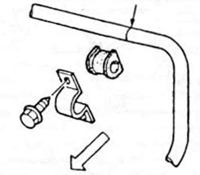
Figure 193. Correct installation of the anti-roll bar. White line (along the arrow) should limit the sleeve with its edge (from both sides) The arrow indicates the direction of movement.
- Tighten the nuts screwed onto the top of the connecting levers until the threaded ends of the levers protrude by 20.1 mm. Mark the dimension with a measuring ruler as shown in the figure 194.
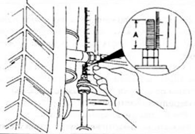
Figure 194. Tighten the anti-roll bar connecting arm nut until the end of the thread between the arrows protrudes by 20.1 mm.
- Hold the nut and lock the second nut so that the position of the first does not change. This will ensure that the rubber mounts are pressed perfectly. The tightening torque of the lock nut is 37-55 Nm.
- Tighten the mounting bracket bolts to 36-54 Nm and lower the vehicle back onto its wheels.
- With four-wheel steering installed, tighten the bolts of both trailing arms to 36-55 Nm.