
1986 and 1987 model year intake air temperature sensor
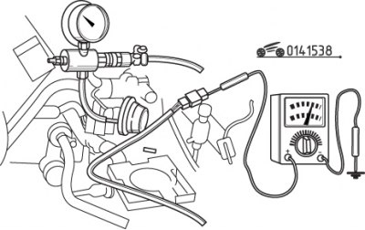
Remove the air filter cover. Ohmmeter connected to the contacts «E2» And «TNA» connector of the air flow meter, measure the resistance of the temperature sensor of the air intake into the engine at various temperatures and compare with the data given in Table. 15.10 (see fig. 15.24).
Table 15.10. The dependence of the resistance of the temperature sensor of the air intake into the engine on temperature
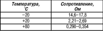
Use a hair dryer to heat the sensor and use dry ice to cool it down tightly around the sensor. If the resistance is out of specification, replace the air flow meter.
Coolant temperature sensor
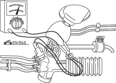
Measure the voltage at the sensor connector pins. To do this, remove the rubber cover from the connector, turn the key in the ignition switch to position «ON» and use a voltmeter to measure the voltage, which should be about 0.05 V. If the voltage is different, measure the resistance of the sensor and check the wires.
Remove the sensor from the engine to check resistance. Immerse the sensor in a glass vessel filled with water and, while heating the water to a boil, measure the resistance at various temperatures. For resistance measurements at low temperatures, pack the sensor tightly with dry ice. The resistance of the coolant temperature sensor depending on the temperature is given in Table. 15.11.
Table 15.11. Dependence of the resistance of the coolant temperature sensor on temperature
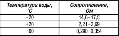
If the resistance differs from the values \u200b\u200bgiven in table. 15.11, replace the sensor.
Before removing the sensor, cool the engine and drain the coolant to a level below the sensor. Disconnect the connector and remove the sensor from the engine. Wrap the sensor threads with Teflon tape before installation.
Atmospheric pressure sensor
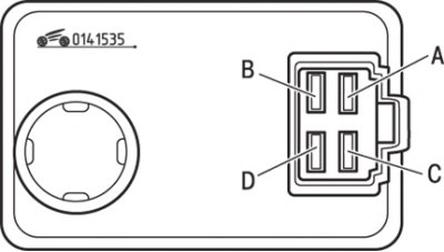
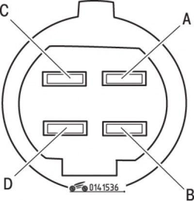
Pic. 15.35. Atmospheric pressure sensor pin assignment
Remove the cap from the sensor and attach the vacuum pump. Turn the key in the ignition switch to position «ON». Measure voltage at each pin with and without vacuum (pic. 15.35). The voltage at the sensor contacts, depending on the vacuum, see table. 15.12.
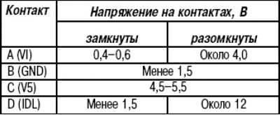
Table 15.12. Voltage at the contacts of the atmospheric pressure sensor depending on the vacuum
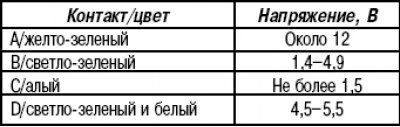
If the voltage at the contacts «A», «WITH» or «D» different from the table, check the wires. If the voltage at the contacts «A», «WITH» or «D» corresponds to the one given in the table, and on the contact «IN» different, replace the sensor.
To replace the sensor, disconnect the connector, unscrew the two bolts and remove the sensor. Installation is carried out in the reverse order of removal.
Thermal sensor
Cool the engine and drain the coolant to a level below the temperature sensor. Disconnect the connector, unscrew the sensor from the radiator and measure its resistance. At temperatures above 13–19°C, the ohmmeter should show a short circuit, otherwise replace the temperature sensor.
Throttle Angle Sensor
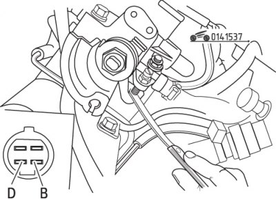
Pic. 15.36. Throttle Angle Sensor Connector Pin Arrangement
Remove the rubber boot from the sensor connector, turn the key in the ignition switch to position «ON». Measure the voltage between the sensor contacts and «weight» and write down the values (pic. 15.36). Fully open the throttle and measure the voltage again. Compare the measurement results with the data given in Table. 15.13.
Table 15.13. Voltage at the contacts of the throttle angle sensor connector depending on the state of the contacts
If from given in table. 15.13 only the voltage on the contact is different «D», check the position of the sensor. If the values on the other pins differ, measure the resistance between the sensor pins.
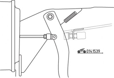
Pic. 15.37. Installing a feeler gauge between the throttle lever and the adjusting screw when checking the resistance between the contacts «IN» And «D»
To check the position of the sensor on 1986 and 1987 models, insert a 0.4 mm feeler gauge between the throttle lever and the adjusting screw (pic. 15.37) and check the connection of the contacts «IN» And «D». Insert a 0.55 mm thick probe, the ohmmeter should show infinity. If the values differ, adjust the sensor by turning it until it is in the correct position.
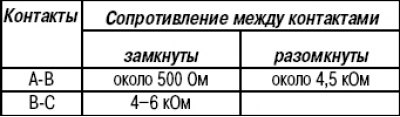
Disconnect the connector from the throttle angle sensor and measure the resistance between the terminals «A» And «IN», «IN» And «WITH» (see fig. 15.36). If the resistance values differ from those given in Table. 15.14, replace the sensor.
Table 15.14. Resistance between the contacts of the throttle angle sensor connector depending on the state of the contacts
To replace the throttle angle sensor, disconnect the connector and remove the two screws. When installing the sensor, align the damper blade with the groove on the sensor, screw the sensor into place and secure with two screws. Adjust the position of the sensor.
Oxygen concentration sensor
To check the oxygen concentration sensor, start the engine and warm up to operating temperature. Disconnect the connector and connect a voltmeter to the sensor side of the connector. Increase the engine speed to 4000 min-1 - the voltmeter should show 0.55 V. Press and release the accelerator pedal several times, reading the readings. With an increase in the speed of rotation, the readings of the voltmeter should be in the range of 0.5–1.0 V, with a decrease in the speed of rotation - 0–0.4 V. If the voltage is different, replace the oxygen concentration sensor.
To replace the sensor, disconnect the connector and unscrew the sensor from the exhaust manifold.
Before installation, replace the sealing washer and coat the threads with an anti-stick compound. Tighten the sensor securely.
Intake manifold pressure sensor (only for early turbocharged engines)
Disconnect the hose from the sensor. Create an air pressure of about 0.6 atm on the sensor.
Attention! The pressure should not exceed 0.85 atm. Otherwise, the valve will fail.
Pic. 15.38. Checking the voltage at the contacts of the pressure sensor connector in the intake manifold when a pressure of 0.6 atm is applied
Measure the voltage on the brown/white wire of the sensor connector (pic. 15.38). When pressure is applied, the reading should not exceed 1.5 V, and when the pressure is removed, it should be about 12 V. If the readings differ, check the wires and the resistance of the sensor.
To check the resistance, disconnect the connector and connect an ohmmeter to the sensor contacts. Create an air pressure of about 0.6 atm on the sensor and read the reading. The ohmmeter should indicate a closed circuit, otherwise replace the sensor.
Power Steering Switch
Pic. 15.39. Resistance measurement between power steering switch connector pins
To test the power steering switch, start the engine and set to idle. Disconnect the connector from the switch and connect an ohmmeter to the switch contacts (pic. 15.39). Ask the assistant to turn the steering wheel all the way to the right or left, while the ohmmeter should show a closed circuit. At any intermediate position of the steering wheel, the ohmmeter should show infinity. If both tests are negative, replace the switch.
Install the new switch on a completely cold engine. With the engine off, turn the steering wheel in both directions to relieve residual pressure in the power steering. Disconnect the connector and remove the switch. Screw in the new switch by hand, after wrapping it with Teflon tape, then tighten it with a wrench. Connect the connector and check the power steering oil level.
Stoplight switch
Disconnect the connector from the brake light switch located under the instrument panel. Connect an ohmmeter to the switch connector contacts and measure the resistance with the brake pedal depressed - the resistance should be zero. Release the pedal - the resistance should be infinity. If the results of both tests are negative, adjust the position of the switch by screwing it in or out.
Pic. 15.40. Location of locknut (1) brake light switch mounting
To replace the switch, disconnect the connector, unscrew the locknut on the side of the switch stem and remove the switch from the bracket (pic. 15.40). Installation is carried out in the reverse order of removal. After installation, adjust the position of the switch.
Clutch Release Sensor
Disconnect the connector from the clutch release sensor and connect an ohmmeter to the sensor connector pins. When the clutch pedal is released, the resistance should be zero, and when pressed, it should be infinity. If the readings are different, adjust the position of the sensor (similar to adjusting the brake light switch).
Neutral position sensor for manual transmission
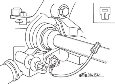
Pic. 15.41. Location of the neutral position sensor of a manual transmission
Disconnect the connector from the neutral position sensor, which is screwed into the gearbox housing (pic. 15.41). Connect an ohmmeter to the sensor terminals and measure the resistance. With the shift lever in neutral, the resistance should be infinity. When any gear is engaged, the ohmmeter should show zero. If the readings are different, replace the sensor. To prevent oil leakage, wrap the sensor threads with Teflon tape when installing.
Deceleration sensor models with automatic transmission
Pic. 15.42. Pin arrangement «A» And «IN» sensor connector (models with automatic transmission)
The deceleration sensor is screwed into the crankcase of the automatic transmission. Disconnect the sensor connector located on the wire and connect an ohmmeter to the contacts «A» And «IN» from the sensor side (pic. 15.42). When the selector lever is set to the positions «parking» or «neutral» the ohmmeter should show zero, and in any other position of the selector, the resistance should be equal to infinity. If the readings are different, replace the sensor.
5th gear enable sensor
Pic. 15.43. Connector Pin Arrangement (1) 5th gear enable sensor
The sensor is screwed into the gearbox housing. Disconnect the connector and connect an ohmmeter to the contacts of the connector located on the wire from the side of the sensor (pic. 15.43). When turning on the 5th gear, the ohmmeter should show infinity, and when turning on any other gear or in the neutral position of the gearbox, the resistance should be zero. If the readings are different, replace the sensor.
To replace the 5th gear sensor, raise the vehicle and secure it on stands. Install a pan under the gearbox and unscrew the sensor from the crankcase. Screw in the new sensor by hand, after wrapping its threads with Teflon tape, and securely tighten with a wrench. Restore the oil level in the gearbox.
Main relay
1986–1987 models
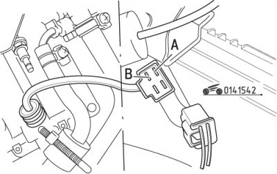
Pic. 15.44. Measurement of voltage on the contacts of the main relay of models 1986-1987
Measure the voltage on each contact of the main relay (pic. 15.44). On contacts «A», «WITH» And «D» voltage should be 12 V, on the contact «IN» - zero. If the voltage values are different, measure the relay resistance.
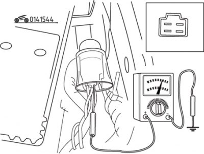
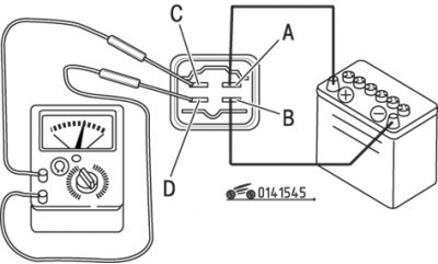
Remove the relay from the car and measure the resistance between the contacts «A» And «IN», which be around 70 ohms. Then apply voltage from the battery to the contact «A» and connect with «weight» contact «IN», while simultaneously observing the resistance between the contacts «WITH» And «D», which should be equal to zero. If both tests fail, replace the relay.
1988-1991 models
Make sure that when you turn the key in the ignition switch to the «ON» And «OFF» the main relay emits a characteristic click.
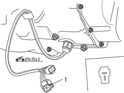
Pic. 15.45. Measuring the resistance between the contacts of the main relay models 1988-1991
Make sure that the resistance between the relay contacts «WITH» And «D» when the relay is powered by a battery, it should be equal to zero, and when the power is turned off, between these contacts should be equal to infinity (pic. 15.45).
Control block
Diagnosis and maintenance of the control unit must be carried out by experienced specialists using special equipment, so contact a car service or a specialized workshop.