
Attention! The power system is under pressure. Before disconnecting the elements of the power system, it is necessary to relieve the pressure in the system. To do this, cover the separation point with a clean rag and, being careful, slowly unscrew the union nut.
Warning! Gasoline is extremely flammable, when working with elements of the power system, the use of fire, sparking devices, open fire hazardous lighting devices, and smoking is prohibited. Sparks should be avoided when working with wires and electrical devices.
Fuel pump
For fuel pump diagnostics and pressure check, see above in subsection «Checking the pressure in the power system».
To check the resistance of the fuel pump, remove the rear seat and disconnect the pump connector.
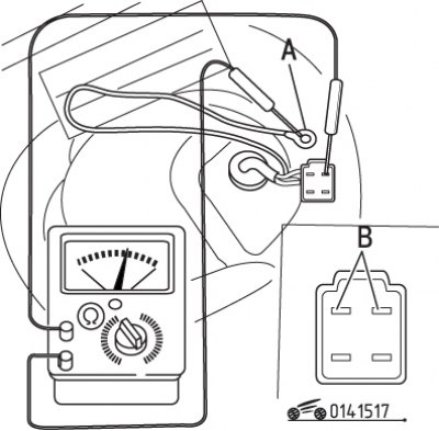
Pic. 15.17. Using an ohmmeter to measure the resistance of the fuel pump: A, B - contacts
Measure resistance between pins «A» And «IN» connector (pic. 15.17). The resistance should be about 0.3 ohm.
To replace the fuel pump, depressurize the fuel supply system, then disconnect the wire from the negative battery terminal.
Remove the service plug and push the rubber seal and wires out of the hole.
Attention! Do not perform the following operations with a full fuel tank. Drain the fuel into a container designed for it, using a pump (it is forbidden to drain gasoline by suction into the hose).
Mark the fuel supply and return pipes with adhesive tape. Loosen the hose clamps and disconnect the hoses.
Turn away bolts of fastening of an arm of the pump and take out from a fuel tank the pump and an arm.
Disconnect the wires from the pump outlets.
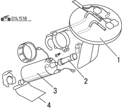
Pic. 15.18. Fuel pump mounting elements: 1 - filter (located inside the tank); 2 - pump; 3 - pump hose; 4 - bracket
Loosen the pump hose clamp screw, move the clamp to the middle of the hose, then remove the pump from the bracket. Remove the pump from the bracket bracket (pic. 15.18).
Remove the rubber cushion and filter from the bottom of the pump by prying and removing the retaining ring for this.
Installation is carried out in the reverse order of removal. Replace gasket between tank and pump bracket.
Pressure Regulator Pilot Valve
The control valve of the pressure regulator is installed on the wall of the engine compartment, between two three-way solenoid distributors. This is a solenoid valve activated by the control unit. The valve, in turn, controls the fuel pressure regulator in accordance with the changing vacuum.
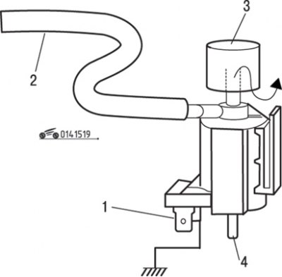
Pic. 15.19. Checking the pressure regulator control valve: 1 - contact for supplying voltage from the battery; 2 - hose; 3 - air filter; 4 - lower valve fitting
To test the valve, put a hose on the top fitting (pic. 15.19). Blow into the hose and make sure air comes out of the bottom fitting. Connect with «weight» one of the filter terminals, and apply voltage from the battery to the other. Blow into the hose and check that air is still escaping from the lower filter fitting. If both tests are negative, replace the filter.
To remove the filter, disconnect the wires and hoses, after marking their location. Remove the valve from the bracket by pulling on the plastic latch. Installation is carried out in the reverse order of removal.
Fuel pressure control
Check fuel pressure.
Reduce the pressure in the fuel supply system, then disconnect the wire from the negative terminal of the battery.
Loosen the fuel return line hose clamp and disconnect the hose from the pressure regulator, after placing a rag to collect spilled fuel.
Remove the vacuum control hose from the regulator.
Remove the two regulator mounting bolts and remove the regulator from the fuel distribution line.
Install pressure regulator with new gasket to fuel rail and secure with bolts.
Connect the fuel return hose and vacuum control hose.
Connect the cable to the negative battery terminal and turn the key in the ignition switch to position «ON». Fill the system to operating pressure by jumpering the diagnostic pins of the fuel pump connector. Check for fuel leaks.
Damper
The damper is installed at the end of the fuel distribution line and is designed to smooth out sharp fuel pressure pulsations that occur when the injectors close and open.
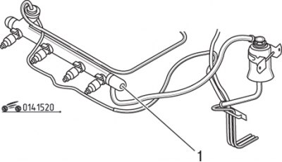
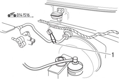
Pic. 15.20. Damper Location (1) at the end of the fuel distribution line
To check the damper, put your finger on the hole at the end - when the engine is running, pulsations should be felt (pic. 15.20). If there is no pulsation, replace the damper.
To replace the damper, reduce the pressure in the power system, then disconnect the wire from the negative terminal of the battery.
Disconnect the pipeline and turn out a damper from a fuel distributive highway.
Installation is carried out in the reverse order of removal.
Fuel distribution line
Reduce the pressure in the power system, then disconnect the wire from the negative terminal of the battery.
Disconnect the fuel return line from the pressure regulator and the line from the damper.
Disconnect connectors from injectors.
Turn out two bolts and carefully disconnect a fuel distributive highway with atomizers from an inlet manifold. Remove the entire assembly by sliding it under the throttle assembly and surge tank.
Installation is carried out in the reverse order of removal. Be sure to inspect the rubber gaskets between the injector and intake manifold and replace them if cracked, hardened or deformed.
Nozzles
For a quick check, place the blade of a long screwdriver in turn against the body of each injector and listen for a click from the needle valves. If clicks are not heard, check the resistance of the injectors.
Remove the fuel distribution line.
To check the tightness of the injectors, connect the hose from the fuel filter to the inlet fitting on the fuel distribution line. Using an additional length of fuel hose and adapter, connect the fuel return line hose to the fuel pressure regulator.
Tie the injectors to the fuel rail to prevent them from falling out when the fuel pressure increases.
Pic. 15.16. Jumper connection (1) contacts of the diagnostic connector for starting the fuel pump
Lay a rag under the nozzles. Turn the key in the ignition switch to position «ON» and, having connected the jumper contacts of the control connector of the fuel pump, start the pump (see fig. 15.16). Watch for dripping or leaking fuel from the injectors. Replace leaking fuel injector.
Attention! A small amount of gasoline is allowed to appear after 5 minutes.
Using an ohmmeter, verify that the resistance between the two pins of each injector is 12-16 ohms. Otherwise, the nozzle is defective and must be replaced.
To replace the nozzle, disconnect the auxiliary hose that was used in the leak test. To prevent fuel from escaping from the hose, wrap it with rags, since it is impossible to reduce fuel pressure in the system with the fuel distribution line removed.
Remove the rubber o-rings and bushings, nozzles and insulators.
It is recommended to periodically replace these elements to eliminate possible fuel leakage.
Install new rubber o-rings, bushings and insulators.
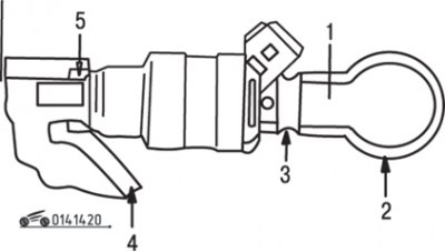
Pic. 14.20. Nozzle Seal Location: 1 - sealing ring; 2 - fuel distribution line; 3 - sealing sleeve; 4 - intake manifold; 5 - insulator
To facilitate installation and reduce the chance of damage, lubricate the O-ring and insulator with a light coat of engine oil (see fig. 14.20).
Insert the injector into the fuel rail with the connector pointing up. The nozzle must be inserted strictly along its axis, otherwise the sealing ring may be damaged.
Establish a fuel distributive highway with atomizers and fasten with bolts. Connect the fuel supply and return hoses and vacuum control hose. Restore pressure in the power system by connecting the jumper contacts of the control connector of the fuel pump, and check the tightness of the system.
Fuel pump relay
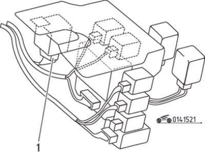
Pic. 15.21. Relay location (1) fuel pump
The fuel pump relay is mounted on the panel under the air spring. It is designed to power the fuel pump while starting the engine with a starter (pic. 15.21). Power is supplied to the pump up to
the starter is turned off, it is at this moment that the relay is automatically unlocked (when the key in the ignition switch passes the position «ON», the pump is not supplied with power, since the motor must be started first).
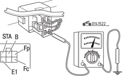
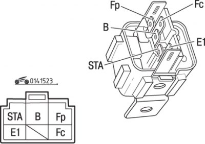
Pic. 15.22. Pin assignment of the self-locking relay connector: Fp - to the fuel pump; Fc - to the fuel pump switch; B - to the ignition switch («ON»)
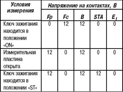
To check the relay and wires, open the measuring plate inside the air flow meter, lock it and measure the voltage on each pin of the relay connector without disconnecting the relay from the connector (pic. 15.22). If the contact voltage «IN» differs from that given in Table. 15.1, check the fuses and wires from the ignition switch.
Table 15.1. Voltage at the contacts of the self-locking relay connector
Pic. 15.23. Position of contacts of the self-latching relay
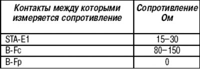
If a voltage deviation is detected on the contact «STA», check the wires from the ignition switch. In case of incorrect indication on the contact «E1» check connection with «weight». If a voltage deviation is detected on the contact «FС», check the resistance of the flow meter or the winding of the relay itself (pic. 15.23). The resistance values at the relay contacts are given in table. 15.2.
Table 15.2. Resistance between contacts of the self-latching relay
If the indication on the contact is different «FP», check the resistance of the self-latching relay.
To replace the relay, disconnect the connector and remove the mounting screw. Installation is carried out in the reverse order of removal.