
MazBook.ru
English Русский
Български
Беларускі
Український
Српски
Hrvatski
Română
Polski
Slovenský
Magyar
• Bookmark • Sitemap • Contacts •   
Cars Opel Cars Ford Cars Volkswagen Cars Audi Cars Kia Cars Renault Cars Peugeot


Familia Capella Mazda3 Mazda6 CX-? Others Articles
Capella 3 (1982-1992, petrol) Capella 3 and 4 (1982-1992) Capella 4 (1987-1992) Capella 5 (1991-1997) Capella 6 (1997-2005, petrol)

Air supply system components (since 1986) (Mazda Capella GC)

  • Home
  • Mazda Capella
  • Capella GC (1982-1992)
  • Power unit
  • Supply system
  • Air supply system components (since 1986)
0
Contents: Throttle assembly ⇓ Checking the air valve ⇓
Remove the two screws and pull the rubber boot off the air flow meter connector.
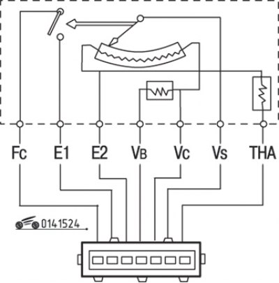
Figure 15.24. Air flow meter connector pinout

Figure 15.24. Air flow meter connector pinout


Turn the key in the ignition switch to the "ON" position and measure the voltage between each connector pin and the "ground" position (figure 15.24). Compare the readings with those given in the table. 15.3.

Table 15.3. Voltage at the air flow meter connector contacts
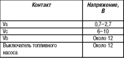


Table 15.3. Voltage at the air flow meter connector contacts

If there is a deviation from the rated voltage, check the main fuse, main meter relay and wires.
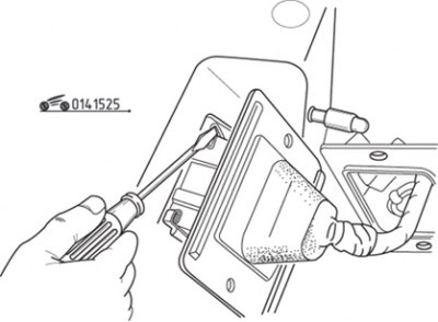
Figure 15.25. Using a screwdriver to release the air flow meter connector retaining clip

Figure 15.25. Using a screwdriver to release the air flow meter connector retaining clip


To disconnect the connector from the air flow meter, release the spring clip by prying it with a small screwdriver (figure 15.25).

Measure the resistance between the connector contacts (see Figure 15.24). The resistance values are given in the table. 15.4.

Table 15.4. Resistance between the contacts of the air flow meter connector in the initial position of the meter plate
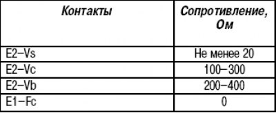


Table 15.4. Resistance between the contacts of the air flow meter connector in the initial position…

Open the measuring plate sharply (by pushing) and measure the resistance between the contacts in accordance with the table. 15.5.

Table 15.5. Resistance between the contacts of the air flow meter connector after deflection of the meter plate
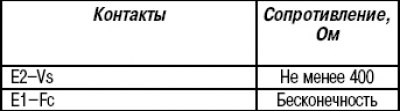


Table 15.5. Resistance between the contacts of the air flow meter connector after deflection of the…

If the resistance deviates from the nominal value, replace the air flow meter.

To replace the air flow meter, loosen the clamp and remove the hose from the upper air cleaner cover. Disconnect the connector and remove the vacuum hose from the air check valve.
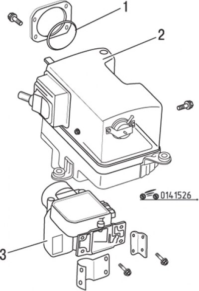


Figure 15.26. Air flow meter mounting elements: 1 – rubber ring; 2 – cover assembly; 3 – air flow…

Figure 15.26. Air flow meter mounting elements: 1 – rubber ring; 2 – cover assembly; 3 – air flow meter


Separate the top air cleaner cover from the base and remove the gauge from the top cover (figure 15.26).

Installation is carried out in the reverse order of removal. Be sure to install the rubber ring between the meter and the top cover.

Caution! The position of the throttle valve adjusting screw is set by the manufacturer; adjustment during vehicle operation is not permitted.


Throttle assembly


Check the smooth movement of the throttle rod. The sticking can be caused by resinous deposits on the back side of the valve, which enter from the crankcase ventilation system through the hose into the surge tank and intake manifold. To remove deposits, remove the throttle body pipe, open the throttle body and thoroughly clean it with fine sandpaper. Be careful not to damage the thin coating of the damper and the housing wall.
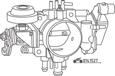
Figure 15.27. Location of throttle body fittings for a non-turbocharged engine
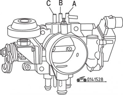
Figure 15.27. Location of throttle body fittings for a non-turbocharged engine


Figure 15.28. Location of throttle body fittings on a turbocharged engine

Figure 15.28. Location of throttle body fittings on a turbocharged engine


Warm up the engine to operating temperature, check the vacuum at each throttle valve connection (figure 15.27, 15.28) and compare the results with the data given in the table. 15.6, 15.7.

Table 15.6. Vacuum pressure at the throttle valve fittings of a non-turbocharged engine
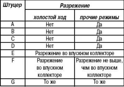


Table 15.6. Vacuum pressure at the throttle valve fittings of a non-turbocharged engine

Table 15.7. Vacuum pressure at the throttle valve fittings of a turbocharged engine
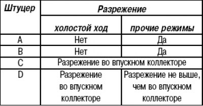


Table 15.7. Vacuum pressure at the throttle valve fittings of a turbocharged engine

If the results are different from what is required, clean or blow out the channels with compressed air.


If you need to remove the throttle body, first disconnect the negative battery cable.

Remove the air duct installed between the throttle body and the air flow meter.

Disconnect the throttle return spring.

Disconnect the throttle control cable from the lever.
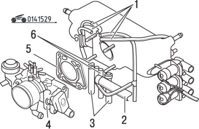
Figure 15.29. Typical throttle assembly fastening elements: 1 – vacuum hose; 2 – air bypass hose; 3…

Figure 15.29. Typical throttle assembly fastening elements: 1 – vacuum hose; 2 – air bypass hose; 3 – coolant hose; 4 – throttle assembly; 5 – gasket; 6 – vacuum hose


Disconnect the vacuum hoses at the top of the throttle body (figure 15.29).

Disconnect the connector from the throttle position sensor.

Drain about 1.0 liters of coolant from the radiator. Disconnect the coolant hose and air bypass hose from the throttle body.

Unscrew the four nuts and remove the throttle assembly.

Use a razor blade to clean off any remaining gaskets from the expansion chamber and throttle body, otherwise air may leak in after the throttle body is installed.

Remove any remaining resinous deposits and dirt from the throttle body by washing it in clean solvent or carbon cleaner. Be especially careful to clean the areas near the throttle valve.

Caution! Do not immerse the throttle angle sensor in any solvent or cleaner. Otherwise, damage to the plastic walls and the electronic circuit located inside is possible.


If possible, blow out the vacuum channels with compressed air.

Installation is carried out in the reverse order of removal.

Checking the air valve
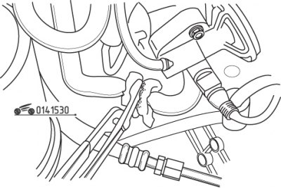


Figure 15.30. Using pliers to clamp the air bypass hose

Figure 15.30. Using pliers to clamp the air bypass hose


Start the engine and let it idle. While the engine is warming up, use pliers to pinch the air bypass hose; the engine crankshaft speed should decrease slightly (figure 15.30). If this does not happen, check the air valve and vacuum hose for leaks.

Warm up the engine to operating temperature. Clamp the hose again; the engine speed should decrease by 100–200 rpm. If the speed decrease exceeds 200 rpm, check for voltage at the air valve connector contacts.

To check the voltage at the air valve connector contacts, disconnect the connector and check the voltage supplied from the battery. If voltage is low or absent, check the fuel pump wiring or relay.

Check the air valve resistance; it should be 30–45 ohms. If the resistance is not within the specified range, replace the air valve.

To check the functionality of the air valve, remove one of the hoses, attach a section of hose and blow out the valve, while the key in the ignition switch must be in the "ON" position.


When the valve temperature is no higher than 20°C, air should pass freely through the valve. At temperatures above 20°C the valve must be closed.

To replace the valve, loosen the clamps and remove the hoses. Disconnect the connector, unscrew the screws and remove the valve.

Installation is carried out in the reverse order of removal.
This article is available at: russian, bulgarian, belarusian, ukrainian, serbian, croatian, romanian, polish, slovak, hungarian
This text was checked by: Georgy Afanasyev
Share with friends on social networks:

Previous
Capella 3 and 4 » Supply system
Next

Fuel supply system components (since 1986)
Checking the fuel system pressure (since 1986)
Reducing pressure in the fuel system (since 1986)
General diagnostics of the electronic fuel injection system (since…
Electronic control system (since 1986)
Air shock absorber (since 1986)
Idle Speed Compensation System (1986 and 1987)
Checking, removing and installing electronic control system…
Turbocharger — inspection, removal and installation (since 1986)
More articles on repairing other Mazda models
Technical characteristics of the power supply system Mazda Familia 5 (1985-1989)
Exhaust system components Mazda3 BK (2003-2009)
Fuel and exhaust system components Mazda6 GG (2002-2008)
Precautions when working with Supplemental Restraint System (SRS)… Mazda CX-5KE (2012-2017)
Safety precautions when working with the air supply system Mazda BT-50 (1) (2006-2011)
Link in different formats to this article
Comments and feedback from visitors
No comments yet


How much will 33 + 48 ?


Capella 6 (1997-2005, petrol) 
  • General information
  • Introduction to guide
  • User manual
  • Troubleshooting
  • Maintenance
  • Power unit
  • 4-cylinder engines
  • 6-cylinder engines
  • Engine overhaul
  • Cooling and ventilation
  • Power and exhaust systems
  • Engine electrics
  • Control system
  • Transmission
  • Mechanical gearbox
  • Automatic gearbox
  • Clutch and drive shafts
  • Chassis
  • Brake system
  • Car suspension
  • Steering
  • Body
  • Exterior (external elements)
  • Interior (internal elements)
  • Doors, windows and locks
  • Electrical equipment
  • Equipment and devices
  • Electrical circuits
Capella 5 (1991-1997) 
  • General information
  • User manual
  • Maintenance
  • Helpful hints
  • Power unit
  • Petrol engines 1.6 and 1.8
  • Petrol engines 2.0
  • 2.5 petrol engines
  • Overhaul engines 1.6 and 1.8
  • Overhaul engines 2.0 and 2.5
  • Diesel engine 2.0
  • Engine electrics
  • Cooling system
  • Air conditioner
  • Carburetor Nikki 30/34
  • Power system (1.6 and 1.8)
  • Power system (2.0 and 2.5)
  • Control system
  • Transmission
  • Mechanical gearbox
  • Automatic gearbox
  • Clutch and axles
  • Chassis
  • Brake system
  • Suspension and wheels
  • Steering
  • Body
  • Exterior (external elements)
  • Interior (internal elements)
  • Doors and windows
  • Electrical equipment
  • Equipment and devices
  • Electrical circuits
Capella 4 (1987-1992) 
  • General information
  • Introduction to manual
  • Vehicle specifications
  • Power unit
  • Engine repair
  • Lubrication system
  • Cooling system
  • Fuel system (carburetor)
  • Fuel injection (FE)
  • Fuel injection (DOHC)
  • Fuel system (diesel)
  • Ignition system
  • Transmission
  • Clutch
  • Gearbox
  • Drive shafts
  • Chassis
  • Front suspension
  • Rear suspension
  • Steering system
  • Brake system
  • Electrical equipment
  • Equipment and devices
  • Electrical circuits
Capella 3 and 4 (1982-1992) 
  • General information
  • User manual
  • Maintenance
  • Power unit
  • Gasoline engine
  • Engine overhaul (gasoline)
  • Diesel engine
  • Cooling and heating
  • Supply system
  • Ignition system
  • Emission reduction
  • Transmission
  • Clutch
  • Mechanical gearbox
  • Automatic gearbox
  • Drive shafts
  • Chassis
  • Brake system
  • Suspension and wheels
  • Steering
  • Body
  • Exterior (external elements)
  • Interior (internal elements)
  • Electrical equipment
  • Equipment and devices
  • Power devices
  • Electrical circuits
Capella 3 (1982-1992, petrol) 
  • General information
  • User manual
  • Maintenance
  • Troubleshooting
  • Late models
  • Power unit
  • Engine in car
  • Engine overhaul
  • Cooling and heating system
  • Fuel and exhaust system
  • Engine electrical system
  • Emission control system
  • Transmission
  • Mechanical gearbox
  • Automatic gearbox
  • Clutch and drive shafts
  • Chassis
  • Brake system
  • Suspension and wheels
  • Steering
  • Body
  • Exterior (external elements)
  • Interior (internal elements)
  • Electrical equipment
  • Equipment and devices
  • Lighting and lamps
  • Electrical circuits
MazBook.ru © 2018–2026 · Mobile version · Articles and news · Sitemap: EN BG BY UA RS HR RO PL SK HU · Feedback · Site search · Add to bookmarks Familia 5 (BF) · Familia 6 (BG) · Capella 3 (GC) · Capella 3 and 4 (GC) · Capella 4 (GD) · Capella 5 (GE) · Capella 6 (GF) · Mazda3 BK · Mazda6 GG · CX-5KE · Mazda 121 (3) · Mazda BT-50 (1) ·
By continuing to use the site, you agree to the use of cookies 🔐