


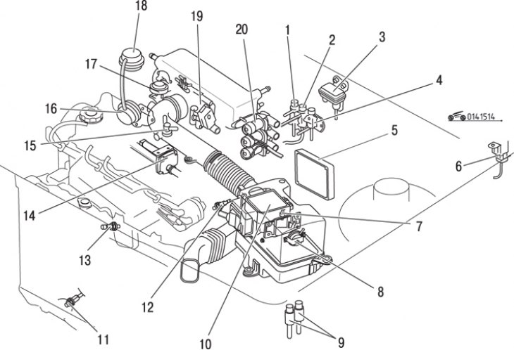
Figure 15.14. Location of components of the electronic control system of a non-turbocharged engine: 1 – three-way electromagnetic distributor; 2 – pressure regulator control valve; 3 – atmospheric pressure sensor; 4 – three-way electromagnetic distributor; 5 – control unit; 6 – fuel pump relay; 7 – intake air temperature sensor; 8 – air control valve; 9 – main relay; 10 – air flow meter; 11 – temperature switch; 12 – analog coolant temperature sensor; 13 – oxygen concentration sensor; 14 – air valve; 15 – thermostat; 16 – exhaust gas recirculation control valve; 17 – pneumatic shock absorber; 18 – recirculation valve with smooth characteristic; 19 – throttle opening angle sensor; 20 – bypass electromagnetic valve
The EGI unit receives signals from a number of sensors that monitor parameters such as intake air volume, air and coolant temperature, crankshaft speed, acceleration or braking mode, and oxygen content in the exhaust gases. Based on this data, the microprocessor unit calculates the injection duration required to maintain the optimal fuel-air mixture ratio. Some sensors and corresponding electromagnetic actuators controlled by the EGI unit are located in the engine compartment and are not part of the unit itself (figure 15.14, 15.15).
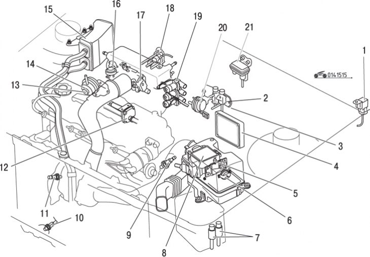
Figure 15.15. Location of components of the electronic control system of a turbocharged engine: 1 – self-releasing fuel pump relay; 2 – pressure regulator control valve; 3 – three-way electromagnetic distributor; 4 – control unit; 5 – intake air temperature sensor; 6 – air control valve; 7 – main relay; 8 – air flow meter; 9 – analog coolant temperature sensor; 10 – temperature switch; 11 – oxygen concentration sensor; 12 – air valve; 13 – exhaust gas recirculation control valve; 14 – position exhaust gas recirculation sensor; 15 – reed valve body; 16 – pneumatic shock absorber; 17 – throttle assembly; 18 – electromagnetic recirculation valve; 19 – bypass electromagnetic valve; 20 – pressure relay; 21 – atmospheric pressure sensor
Original material on the website MAZBOOK.ru
Caution! The fuel system is under pressure. Before disconnecting the fuel system components, it is necessary to relieve the pressure in the system. To do this, cover the disconnected area with a clean cloth and, being careful, smoothly unscrew the union nut.
Warning! Gasoline is extremely flammable. When working with fuel system components, do not use open flames, sparking devices, open fire-hazardous lighting devices, or smoke. Avoid sparks when working with wires and electrical devices.