


Stop the engine and connect the tachometer.
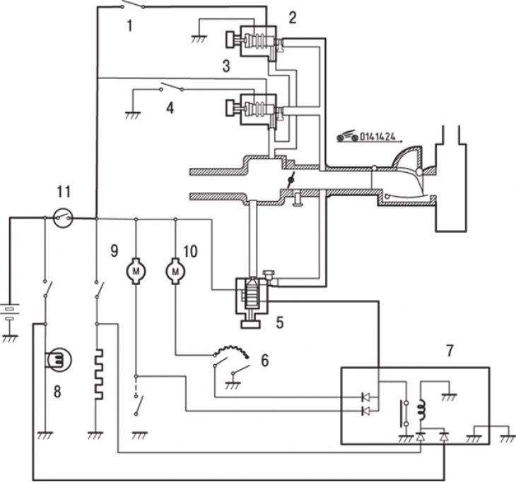
Figure 14.24. Schematic diagram of the engine warm-up system: 1 – air conditioning switch; 2, 4, 5 – electromagnetic valves; 3 – electromagnetic valve of the power steering; 6 – fan switch; 7 – control unit; 8 – headlights; 9 – radiator fan motor; 10 – fan motor; 11 – ignition switch
Disconnect the connectors from the radiator fan motor and the air conditioner magnetic clutch (figure 14.24).
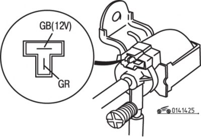
Figure 14.25. Engine warm-up valve connector pin location
Apply voltage from the battery to the "GB" terminal of the engine warm-up valve and start the engine (figure 14.25). If all electrical consumers are turned off, the engine speed should be 1200–1300 min⁻¹. Otherwise, adjust the valve by turning the adjusting screw.
Stop the engine, connect the connectors and remove the tachometer.
The original article is available on: Mazbook