
All four injectors open at the same time, once per revolution of the crankshaft, which provides two injections of fuel per cycle.
Check, removal and installation
Start the engine and warm it up to normal operating temperature, then let it idle.
For a quick check, place the blade of a long screwdriver in turn against the body of each injector and listen for clicks coming from the needle valves. A faulty injector will not click, in which case further verification is necessary.
Leave the engine running at idle and disconnect the connectors from each injector in turn. The engine speed should decrease by 100-2200 min-1 when disconnecting the connector from each injector.
Stop the engine and disconnect the connectors from the injectors. Using an ohmmeter, verify that the resistance between the two pins of each injector is 12-16 ohms. Otherwise, the nozzle is defective and must be replaced.
To remove the injector, disconnect the wire from the negative terminal of the battery.
If the engine is hot, wait until it cools down.
Disconnect the fuel hoses from the fuel filter and pressure regulator. To prevent fuel splashing, wrap the hoses with a cloth before disconnecting them.
Disconnect connectors from all injectors.
Turn out bolts of fastening of a regulator of pressure to an end face of a fuel distributive highway.
Turn out bolts and remove a fuel distributive highway from atomizers.
Remove the rubber o-rings and bushings, nozzles and insulators.
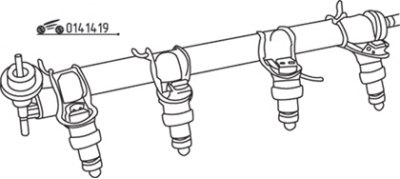
Pic. 14.19. Injectors attached to the fuel rail for testing
To further check the injectors, install them on the fuel distribution line and secure with wires (pic. 14.19).
Temporarily connect the fuel distribution line between the fuel filter and the fuel return line.
Connect the wire to the negative terminal of the battery and turn on the ignition.
Connect the terminals of the fuel pump control connector with a piece of wire and make sure that gasoline does not ooze from the ends of the injectors (see fig. 14.16). The appearance of a small amount of gasoline after 5 minutes is acceptable.
To check the volume of fuel injected by the injector, a measuring vessel, wires and a 12V power supply are required.
Working with each nozzle in turn, slide the end of the plastic tube over the end of the nozzle and place the other end into the measuring vessel.
Connect the fuel pump control connector terminals and turn on the ignition.
Apply 12 volts to the injector for 15 seconds and check that the volume of injected fuel is 44-62 cm3.
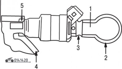
Pic. 14.20. Nozzle Seal Location: 1 - sealing ring; 2 - fuel distribution line; 3 - sealing sleeve; 4 - intake manifold; 5 - insulator
Remove the instrumentation and reinstall the injectors. Installation is carried out in the reverse order of removal, while installing new rubber o-rings (pic. 14.20). Dip them in gasoline right before installing them and installing the fuel rail.