


Removal and installation
Disconnect the cable from the negative battery terminal.
Remove the air filter.
Disconnect the accelerator cable and cruise control cable from the carburetor (if it exists).
Disconnect the fuel supply hoses from the carburetor.
Disconnect the contact connectors from the carburetor.
Disconnect the choke control cable (in models with manual air damper control).
Disconnect the vacuum hoses from the carburetor, after marking their location.
Remove the nuts and lift the carburetor so that the air damper heater wire can be disconnected (only on models with automatic air damper control), then remove the carburetor from the intake manifold.
Use a screwdriver to remove the gasket or seal from the intake manifold.
Installation is carried out in the reverse order of removal, taking into account the following.
Fill the carburetor float chamber with gasoline, which will make the engine easier to start and reduce the load on the battery.
Replace the gaskets on both sides of the spacer.
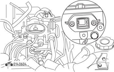
Figure 6.4. Checking the fuel level in the float chamber through the inspection window
After installation, start the engine, check for fuel leaks and ensure that the fuel level in the float chamber exactly matches the mark on the sight glass (figure 6.4). If the fuel level does not match the mark, adjust the carburetor.
Check the engine idle speed and CO content in the exhaust gases.
Carburetor repair and adjustment
Attention! A complete carburetor overhaul is a complex operation that requires specific skills. An inexperienced car owner should contact a service center or auto repair shop.
Please note: Due to design changes made by the manufacturer, some components of the repaired unit may differ from those installed on your carburetor. However, a car enthusiast with some experience in carburetor repairs can identify these differences and perform repairs.
Disassembly
Before starting work, find out the cost and availability of spare parts. It may be more expedient to purchase a new carburetor than to repair a clearly worn-out unit.
Clean the outside of the carburetor with solvent and dry it. Place the carburetor on a clean, well-lit work bench. Prepare a large number of small containers and markers.
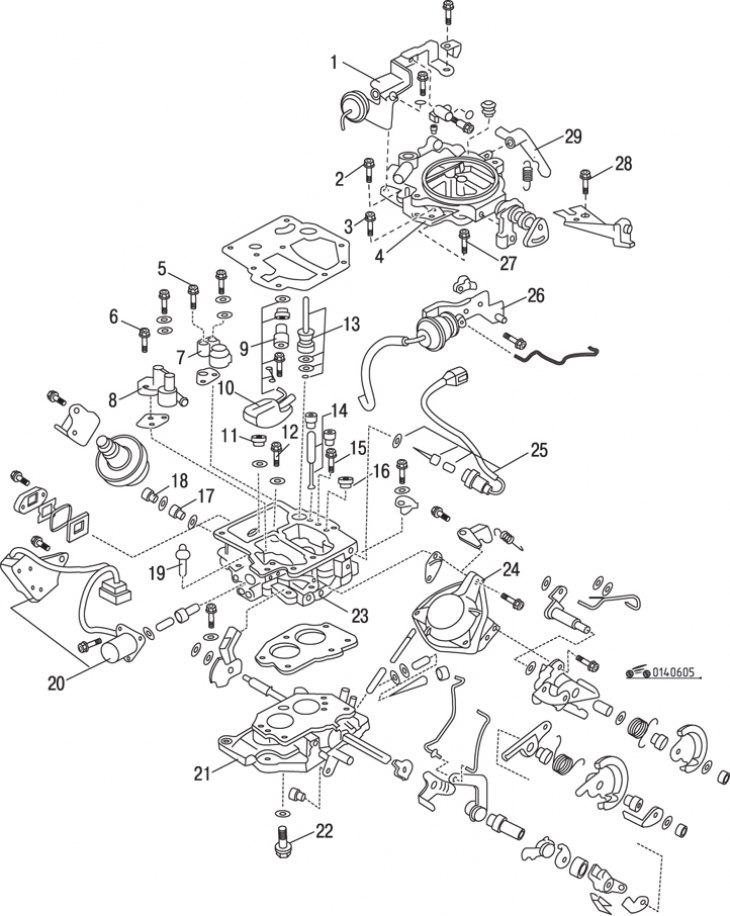
Figure 6.5. Carburetor parts: 1 – diaphragm of the pneumatic drive of the air damper opening device with a bracket; 2, 3, 27, 28 – screws; 4 – air damper housing; 5 – air jet of the main metering system of the primary chamber; 6 – air jet of the main metering system of the secondary chamber; 7 – large and small diffusers of the primary chamber; 8 – large and small diffusers of the secondary chamber; 9 – needle valve; 10 – float; 11 – main fuel jet of the primary chamber; 12 – power jet; 13 – accelerator pump; 14 – primary chamber idle system fuel jet; 15 – accelerator pump check valve; 16 – air jet of the idle system of the primary chamber No. 2; 17 – main fuel jet of the secondary chamber; 18 – plug; 19 – primary chamber idle system fuel jet; 20 – electromagnetic valve for depleting the air-fuel mixture when coasting and forced idle switch; 21 – throttle body; 22 – bolt; 23 – carburetor body; 24 – diaphragm of the pneumatic drive of the secondary chamber throttle valve; 25 – idle fuel cut-off valve; 26 – diaphragm of the pneumatic drive of the starting device with a bracket; 29 – accelerator pump drive lever
Carefully inspect the throttle and air valve drive linkages and the accelerator pump. Draw or label them if they differ from those shown in the figure 6.5.
Disconnect the accelerator pump drive lever from the throttle linkage. Unhook the lever spring.
Disconnect the starting device's pneumatic drive hose from the nozzle on the throttle body.
Separate the fast idle system push rod from the choke shaft drive lever.
Remove the eight screws securing the air damper housing to the carburetor body. The screw lengths vary, so it is necessary to mark their locations.
Lift the air damper housing, moving the wires to the side. Leave the gasket in place. The accelerator pump piston can be removed together with the housing.
Clean the float chamber and remove the fuel and air jets.
Remove the float shaft from the air damper housing, remove the float and needle valve, then unscrew the needle valve seat.
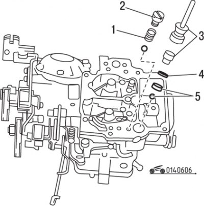
Figure 6.6. Accelerator pump parts: 1 – limiting spring ring and ball of the accelerator pump check valve; 2 – control valve plug; 3 – accelerator pump piston assembly; 4 – retaining ring; 5 – filter and inlet ball of the accelerator pump valve
Remove the idle fuel shut-off valve, then reinstall the accelerator pump spring and piston (figure 6.6).
Remove the air shock absorber, the solenoid valve for leaning the fuel-air mixture when coasting and the forced idle switch (if they are provided for by the design).
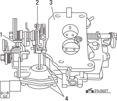
Figure 6.7. Location of the throttle rod (1), diaphragm pusher (2), throttle body (3) and diaphragm assembly (4)
If necessary, the secondary throttle body and air damper drive diaphragms can be removed together with the brackets. The secondary throttle actuator diaphragm can only be disassembled for inspection, as spare parts are not available (figure 6.7).
If you need to separate the throttle body from the carburetor body, keep in mind that one of the mounting screws is located at the bottom, near the secondary chamber valve.
Unscrew the idle mixture screw, remembering the number of revolutions to which it was screwed in, so that later you can install the screw in approximately the same place.
Cleaning and checking
Wash all parts with solvent and blow with compressed air. If you don't have a compressor, you can use compressed air from a cylinder. It is not allowed to clean the jets and channels with wire.
Do not immerse the idle shut-off valve, actuator diaphragms, or other rubber or plastic components in the solvent, as they may harden, swell, or become misshapen.
Make sure all fuel passages, jets and other calibrated components are free of dirt and burrs.
Check for damage to the top and bottom surfaces of the choke housing, carburetor housing and throttle body. Make sure there are no gasket residues on them.
Visually inspect the holes for the drive levers and plastic bushings for wear and ovality; replace any heavily worn parts.
Check the float needle valve and float seat for cleanliness and wear; replace parts with noticeable deep wear and scratches.
Check for deformations on the float, float levers and axle, straighten the deformed parts by bending them, replace them if necessary.
Check the accelerator pump rubber cap for wear and cracks.
Check the wear of the idle mixture adjustment screw (presence of burrs and ring wear).
Check the wear of the air damper plate and the degree of deformation of the rod. If the deformation is severe, bend the rod.
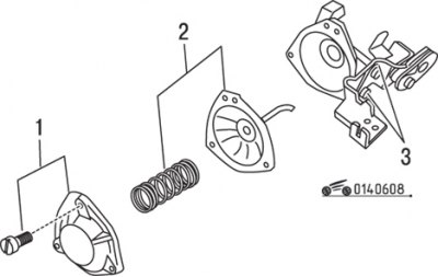
Figure 6.8. Pneumatic actuator diaphragm: 1 – cover and screw; 2 – spring and diaphragm; 3 – throttle valve drive lever
Check the air damper pneumatic actuator diaphragm for leaks and replace it if necessary (figure 6.8).
Check if the air damper rotates freely.
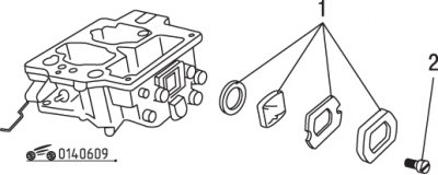
Figure 6.9. Carburetor body inspection window: 1 – lining, gasket, glass and rubber gasket; 2 – screw
If necessary, unscrew the screws, remove and clean the inspection window elements of the carburetor body (figure 6.9).
Check the serviceability of the solenoid valve winding by connecting the terminal to the positive terminal of the battery and the housing to the vehicle ground. When current passes through the coil, the valve stem should be pulled into the housing. If this does not happen, replace the valve.
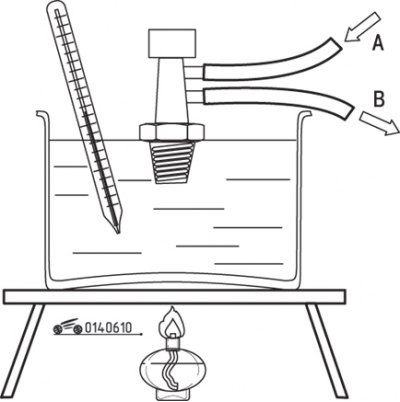
Figure 6.10. Checking the thermal valve of the automatic air damper opening device: A – air inlet; B – air outlet
The vacuum level in the diaphragm of the pneumatic drive of the automatic air damper opening device is controlled by a thermal valve, which is screwed into the intake manifold housing. The valve should not allow air to pass through at temperatures below 19°C and should open fully at temperatures above 19°C. The operating temperature range is ±3°C. If desired, check the valve for proper operation by unscrewing it (figure 6.10).
Assembly
Assembly is carried out in the reverse order of disassembly, taking into account the following.
Replace all gaskets.
Turn the idle mixture adjustment screw back in by the same number of revolutions that was determined when it was turned out.
During assembly, make all adjustments listed below.
Adjusting the position of the float on the air damper body
Before installing the air damper housing, it is necessary to measure the distance between the bottom surface of the float and the plane of the housing (without gasket) and adjust the position of the float. To do this, follow these steps:
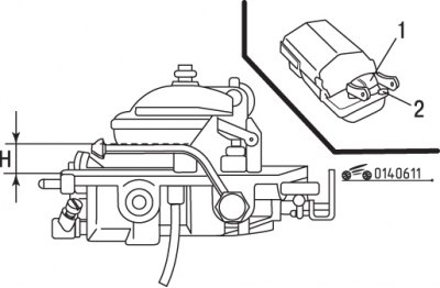
Figure 6.11. Measuring and adjusting the float position (the body is turned over): 1 – float tongue; 2 – limiter; H – gap
- turn the body upside down so that the float sinks under its own weight, and measure the gap between the float and the body surface. Compare the measured value (dimension H in Figure 6.11) with the required value and, if necessary, bend the float tongue;
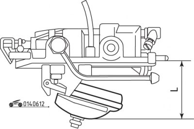
Figure 6.12. Measuring and adjusting the float position (the body is in working position): L – gap
- turn the body over with the float facing down so that the float sinks under its own weight, and measure the distance between the bottom surface of the float and the plane of the body. If the measured value (size L in figure 6.12) does not correspond to the required value, adjust it by bending the float limiter.
Adjusting the air damper opening device clearance
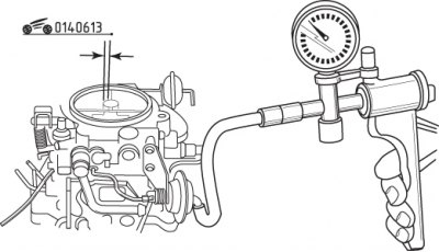
Figure 6.13. Using a vacuum pump to check the air damper opening clearance
Apply a vacuum of approximately 400 mmHg to the diaphragm vacuum tube (figure 6.13).
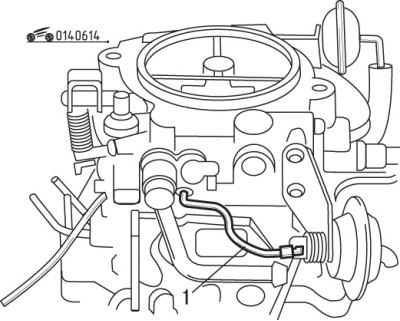
Figure 6.14. Location of the air damper opening device rod (1)
Close the air damper with a light push and measure the gap. The nominal clearance is (3.94±0.16) mm. If clearance adjustment is necessary, bend the rod (figure 6.14).
Adjusting the diaphragm gap of the starting device
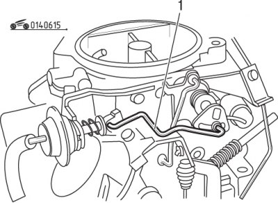
Figure 6.15. Location of the diaphragm rod (1) of the starting device
The check is performed in the same way as for the air damper opening device, but the gap size should be 1.94 + 0.25 mm. If the gap needs to be adjusted, bend the rod (figure 6.15).
Fast idle

Figure 6.16. Location of the fast idle drive rod (1)
Close the air damper completely and use a drill bit or a round gauge to measure the gap between the primary chamber damper and the diffuser wall. The nominal value is given in the technical data. If necessary, adjust the clearance by bending the fast idle drive rod (figure 6.16).
Adjusting the throttle lever
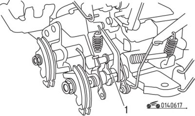
Figure 6.17. Location of the throttle valve drive lever (1)
Check the opening of the secondary chamber throttle valve. It should open only after the primary throttle valve is rotated by 45°. At this angle, the clearance between the primary throttle valve and the wall is (6.7±0.5) mm. At a smaller rotation angle, the secondary throttle valve should not be noticeable. Also, make sure the secondary chamber flap rotates freely with the primary chamber flap fully open. If necessary, make adjustments by bending the damper drive lever (figure 6.17).
Caution! Since the secondary chamber flap is designed for pneumatic actuation, it must be operated manually.
Adjusting the quantity and quality of the air-fuel mixture at idle
Install the carburetor, warm up the engine and adjust the engine idle speed and mixture quality. After adjustment, install new protective caps on the screws.