
MazBook.ru
English Русский
Български
Беларускі
Український
Српски
Hrvatski
Română
Polski
Slovenský
Magyar
• Bookmark • Sitemap • Contacts •   
Cars Opel Cars Ford Cars Volkswagen Cars Audi Cars Kia Cars Renault Cars Peugeot


Familia Capella Mazda3 Mazda6 CX-? Others Articles
Capella 3 (1982-1992, petrol) Capella 3 and 4 (1982-1992) Capella 4 (1987-1992) Capella 5 (1991-1997) Capella 6 (1997-2005, petrol)

Engine idling crankshaft speed compensator (Mazda Capella GC)

  • Home
  • Mazda Capella
  • Capella GC (1982-1992)
  • Power unit
  • Supply system
  • Engine idling crankshaft speed compensator
0
Contents: Servo diaphragm ⇓ Three-way valve ⇓ Power steering switch ⇓
The idle speed compensator, provided on some models, is designed to automatically increase the engine idle speed, which decreases under the effect of additional load from the air conditioning compressor drive and/or power steering. The compensator consists of a servo diaphragm, the design of which depends on how the car is equipped - with an air conditioning system and a power steering system or only with an air conditioning system and a three-way electromagnetic valve. A system malfunction is manifested by a decrease in the engine crankshaft speed at idle when the air conditioner and/or power steering are operating.

Servo diaphragm


Remove the air filter.

Turn off all consumers and disconnect the contact connector from the electric cooling fan.

Disconnect and plug the idle air compensator hoses, reed valves and temperature sensor.

Warm up the engine to operating temperature and connect the tachometer.

Models equipped with air conditioning
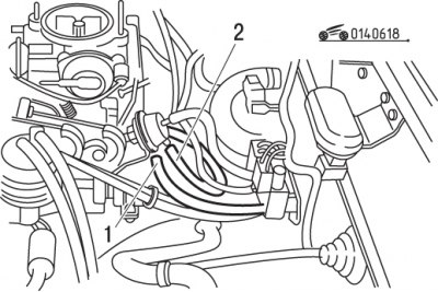


Figure 6.18. Checking the engine crankshaft speed compensator at idle speed (on models equipped…

Figure 6.18. Checking the engine crankshaft speed compensator at idle speed (on models equipped with air conditioning): 1 – vacuum control tube; 2 – vacuum supply tube during testing


Disconnect vacuum tube 1 (figure 6.18).

Caution! Apply vacuum to the hose and diaphragm through the tee; the engine crankshaft speed should increase to 1200–1450 min⁻¹


. If necessary, set the specified engine crankshaft speed by turning the adjusting screw (figure 6.19).
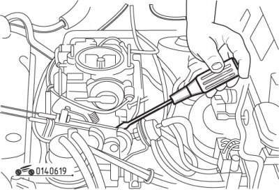
Figure 6.19. Adjusting the diaphragm of the engine crankshaft speed compensator at idle speed (on…

Figure 6.19. Adjusting the diaphragm of the engine crankshaft speed compensator at idle speed (on models equipped with air conditioning)


Models equipped with power steering


Remove the air filter.

Turn off all consumers and disconnect the contact connector from the electric cooling fan.

Disconnect and plug the idle air compensator hoses, reed valves and temperature sensor.

On models equipped with air conditioning, check and adjust the servo diaphragm.
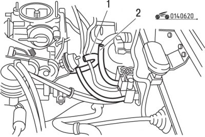
Figure 6.20. Checking the engine speed compensator diaphragm at idle speed (on models equipped with…

Figure 6.20. Checking the engine speed compensator diaphragm at idle speed (on models equipped with power steering): 1 – vacuum control tube; 2 – vacuum supply tube during testing


Disconnect vacuum tube 1 (figure 6.20) and through the tee apply vacuum to the hose and diaphragm.

Engine speed should increase to 800–1000 rpm for models with a manual transmission and to 1050–1250 rpm for models with an automatic transmission. If necessary, disconnect the vacuum hose and set the desired speed by turning the adjusting screw (figure 6.21).
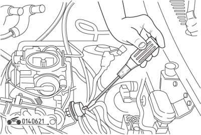
Figure 6.21. Adjusting the diaphragm of the engine crankshaft speed compensator at idle speed (on…

Figure 6.21. Adjusting the diaphragm of the engine crankshaft speed compensator at idle speed (on models equipped with power steering)


Reconnect the vacuum hose and check the engine idle speed again.

Three-way valve


A three-way valve is connected between the intake manifold and the servo diaphragm.
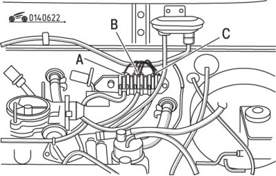
Figure 6.22. Purpose of controlled vacuum channels on a three-way solenoid valve: A – power…

Figure 6.22. Purpose of controlled vacuum channels on a three-way solenoid valve: A – power steering valve; B – ACVN air conditioner valve₂; C – air conditioning valve


On models equipped with air conditioning, the three-way valve shuts off the vacuum supply in accordance with a signal sent to the control unit from the air conditioning switch. On models equipped with power steering, a three-way valve cuts off the vacuum supply in accordance with a signal from the power steering switch (figure 6.22).
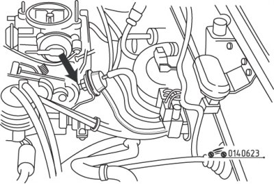
Figure 6.23. Extending the servo diaphragm rod with a serviceable three-way valve

Figure 6.23. Extending the servo diaphragm rod with a serviceable three-way valve


The primary source is the website: mazbook.ru

Turn on the air conditioner (the engine should idle). If the valve is working properly, the servo diaphragm rod extends (figure 6.23).

Turn off the air conditioner and turn the steering wheel all the way to the right or left. If the three-way valve and power steering switch are in good working order, the servo diaphragm rod will extend.

Power steering switch
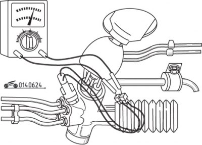


Figure 6.24. Checking the power steering switch circuit

Figure 6.24. Checking the power steering switch circuit


Disconnect the connector from the power steering switch and check the circuit through the switch as shown in the figure 6.24. With the engine idling, turn the steering wheel all the way to the right or left – the switch should be in the closed position.
This article is available at: russian, bulgarian, belarusian, ukrainian, serbian, croatian, romanian, polish, slovak, hungarian
This text was checked by: Georgy Afanasyev
Share with friends on social networks:

Previous
Capella 3 and 4 » Supply system
Next

Carburetor — removal, inspection and installation
Fuel tank — removal and installation
Repair and replacement of fuel lines
Fuel pump — inspection, removal and installation
General information about the power supply system
Air damper control cable
Elements of the exhaust system
Power supply system malfunctions, their causes and troubleshooting…
Carburetor — removal, inspection and installation (since 1984)
Distributed fuel injection system (since 1984)
More articles on repairing other Mazda models
Adjusting engine idle speed Mazda Familia 5 (1985-1989)
Tachometer (engine speed) Mazda3 BK (2003-2009)
Tachometer (engine speed indicator) Mazda6 GG (2002-2008)
Emergency engine start Mazda CX-5KE (2012-2017)
Starting the engine from an auxiliary battery Mazda 121 (3) (1996-2003)
Link in different formats to this article
Comments and feedback from visitors
No comments yet


How much will 22 + 29 ?


Capella 6 (1997-2005, petrol) 
  • General information
  • Introduction to guide
  • User manual
  • Troubleshooting
  • Maintenance
  • Power unit
  • 4-cylinder engines
  • 6-cylinder engines
  • Engine overhaul
  • Cooling and ventilation
  • Power and exhaust systems
  • Engine electrics
  • Control system
  • Transmission
  • Mechanical gearbox
  • Automatic gearbox
  • Clutch and drive shafts
  • Chassis
  • Brake system
  • Car suspension
  • Steering
  • Body
  • Exterior (external elements)
  • Interior (internal elements)
  • Doors, windows and locks
  • Electrical equipment
  • Equipment and devices
  • Electrical circuits
Capella 5 (1991-1997) 
  • General information
  • User manual
  • Maintenance
  • Helpful hints
  • Power unit
  • Petrol engines 1.6 and 1.8
  • Petrol engines 2.0
  • 2.5 petrol engines
  • Overhaul engines 1.6 and 1.8
  • Overhaul engines 2.0 and 2.5
  • Diesel engine 2.0
  • Engine electrics
  • Cooling system
  • Air conditioner
  • Carburetor Nikki 30/34
  • Power system (1.6 and 1.8)
  • Power system (2.0 and 2.5)
  • Control system
  • Transmission
  • Mechanical gearbox
  • Automatic gearbox
  • Clutch and axles
  • Chassis
  • Brake system
  • Suspension and wheels
  • Steering
  • Body
  • Exterior (external elements)
  • Interior (internal elements)
  • Doors and windows
  • Electrical equipment
  • Equipment and devices
  • Electrical circuits
Capella 4 (1987-1992) 
  • General information
  • Introduction to manual
  • Vehicle specifications
  • Power unit
  • Engine repair
  • Lubrication system
  • Cooling system
  • Fuel system (carburetor)
  • Fuel injection (FE)
  • Fuel injection (DOHC)
  • Fuel system (diesel)
  • Ignition system
  • Transmission
  • Clutch
  • Gearbox
  • Drive shafts
  • Chassis
  • Front suspension
  • Rear suspension
  • Steering system
  • Brake system
  • Electrical equipment
  • Equipment and devices
  • Electrical circuits
Capella 3 and 4 (1982-1992) 
  • General information
  • User manual
  • Maintenance
  • Power unit
  • Gasoline engine
  • Engine overhaul (gasoline)
  • Diesel engine
  • Cooling and heating
  • Supply system
  • Ignition system
  • Emission reduction
  • Transmission
  • Clutch
  • Mechanical gearbox
  • Automatic gearbox
  • Drive shafts
  • Chassis
  • Brake system
  • Suspension and wheels
  • Steering
  • Body
  • Exterior (external elements)
  • Interior (internal elements)
  • Electrical equipment
  • Equipment and devices
  • Power devices
  • Electrical circuits
Capella 3 (1982-1992, petrol) 
  • General information
  • User manual
  • Maintenance
  • Troubleshooting
  • Late models
  • Power unit
  • Engine in car
  • Engine overhaul
  • Cooling and heating system
  • Fuel and exhaust system
  • Engine electrical system
  • Emission control system
  • Transmission
  • Mechanical gearbox
  • Automatic gearbox
  • Clutch and drive shafts
  • Chassis
  • Brake system
  • Suspension and wheels
  • Steering
  • Body
  • Exterior (external elements)
  • Interior (internal elements)
  • Electrical equipment
  • Equipment and devices
  • Lighting and lamps
  • Electrical circuits
MazBook.ru © 2018–2026 · Mobile version · Articles and news · Sitemap: EN BG BY UA RS HR RO PL SK HU · Feedback · Site search · Add to bookmarks Familia 5 (BF) · Familia 6 (BG) · Capella 3 (GC) · Capella 3 and 4 (GC) · Capella 4 (GD) · Capella 5 (GE) · Capella 6 (GF) · Mazda3 BK · Mazda6 GG · CX-5KE · Mazda 121 (3) · Mazda BT-50 (1) ·
By continuing to use the site, you agree to the use of cookies 🔐