
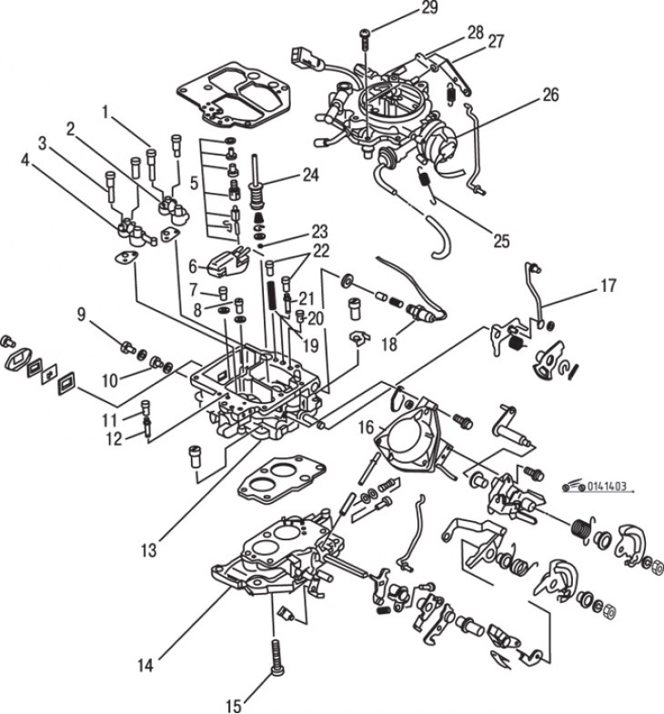
Pic. 14.3. Carburetor equipped with automatic choke control: 1 - air jet of the primary chamber; 2 – primary chamber economizer and economizer atomizer; 3 - air jet of the secondary chamber; 4 - economizer of the secondary chamber and economizer spray; 5 - needle valve; 6 - float; 7 - the main jet of the primary chamber; 8 - screw for adjusting the quality of the air-fuel mixture; 9 - plug; 10 - the main jet of the secondary chamber; 11 - plug; 12 - idle jet of the secondary chamber; 13 - carburetor body; 14 - the base of the carburetor; 15 - bolt (with vacuum channel); 16 - diaphragm of the secondary chamber; 17 - damper rod; 18 - solenoid valve for fuel cut-off at idle; 19 - balancing channel; 20 - air jet of the primary chamber of the idle system (№2); 21 - idle jet of the primary chamber; 22 - plug; 23 - check valve of the accelerator pump; 24 - accelerating pump; 25 - spring; 26 - air damper with automatic control; 27 - lever; 28 - air cap; 29 - screw
The carburetor of later models with 2.0 L engine is equipped with an automatic choke instead of the manual choke found on earlier models. The damper actuator consists of a bimetallic spring, which is heated by electric current and opens the damper for a time, the duration of which depends on the air temperature (pic. 14.3).
Apart from the presence of an automatic choke, the design of the carburetor is practically the same as the design of the carburetor of earlier years of production.
Air damper with automatic control
Removal and installation
Remove the air filter and disconnect the power wire from the automatic air damper.
Loosen the screws, remove the cover and at the same time disconnect the bimetal spring from the damper drive lever.
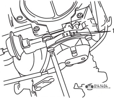
Pic. 14.4. Label Alignment (1)
Installation is carried out in the reverse order of removal; Align the mark on the cover with the center mark on the body before tightening the screws (pic. 14.4).
Check and adjustment
Check the conductivity of the heating winding of the automatic air damper by disconnecting the power wire from it and connecting the ohmmeter probes to the winding wire and «mass» car. If the ohmmeter shows «infinity», which means that there is a break in the winding and the air damper cover must be replaced.
The operation of adjusting the damper diaphragm is similar to the operation given in subsection «Repair and adjustment of the carburetor».
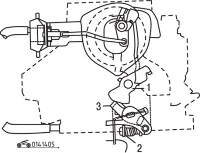
Pic. 14.5. Gap adjustment elements (G) idle systems: 1 – a cam of system of idling; 2 - adjusting screw; 3 – the lever of system of idling
To adjust the idle throttle opening, open the throttle, lower the lever to the second upper cam stage. Check the gap between the throttle valve of the primary chamber and the wall, which should be 0.94–1.38 mm. If necessary, adjust it by turning the adjusting screw (pic. 14.5).
The operation of checking the throttle valve opening is similar to the operation given in subsection «Repair and adjustment of the carburetor» (see «Power supply system for gasoline engines»), while the primary chamber damper must be opened by 50°before the secondary chamber damper begins to open. Nominal size 7.32–8.28 mm.
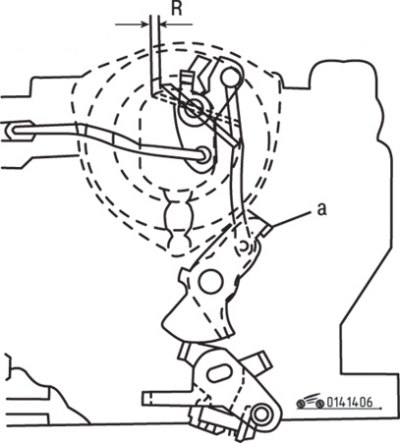
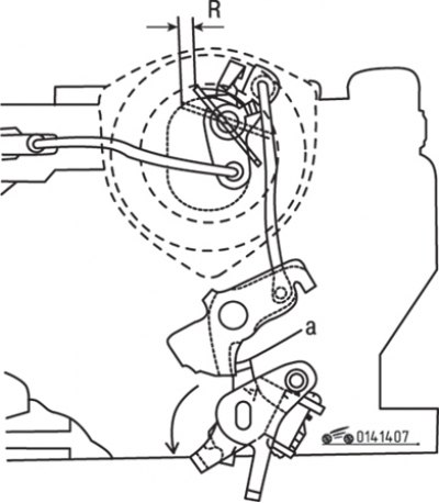
Pic. 14.6. Gap measurement point (R) throttle valve when the engine is idling: a - adjusting tongue
To adjust the throttle opening when the engine is idling, open the throttle and lower the lever to the second highest cam stage (pic. 14.6). Check that the gap between the upper edge of the throttle valve and the wall is between 0.60 and 1.00 mm. If slight adjustment is needed, bend the tab on the drive lever. If significant adjustment is needed, bend the actuator linkage.
Pic. 14.7. Gap adjustment elements (R) carburetor safety valve: a - adjusting tongue
To adjust the safety valve, fully open the primary chamber damper, then check that the gap between the upper edge of the primary chamber damper and the wall is 0.07–0.51 mm; if necessary, bend the tongue (pic. 14.7).
To test the throttle at idle, warm up the engine to normal operating temperature, then stop the engine and remove the air filter. Open the throttle slightly, then fully close the throttle valve and release the throttle. The idle cam will hold the primary throttle open in the idle position. Connect the tachometer, then, without depressing the accelerator pedal, start the engine and make sure that the engine crankshaft rotates at a frequency of 3000–4000 rpm-1. If necessary, adjust the engine speed by turning the idle adjustment screw. Stop the engine, disconnect the tachometer and reinstall the air filter.