


Contents: Checking the throttle assembly ⇓ Removal and installation the…⇓ Checking and adjusting the throttle…⇓
The throttle body is located behind the air flow meter and is attached to the expansion chamber. It is equipped with a throttle valve which is connected to the accelerator pedal; idle bypass system; throttle position sensor; damper to control the closing of the throttle valve. The throttle position sensor sends a signal to the control unit.
Checking the throttle assembly
Turn the throttle lever and make sure it moves easily. When free, the lever should touch the throttle stop screw. If necessary, clean the axle components and check the damper for sticking.
Start the engine and warm it up to normal operating temperature.
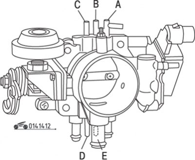
Figure 14.12. Channel arrangement (A, B, C, D, E) throttle body of the RVT system
Set the idle speed, then disconnect the hoses one by one and check the pressure in the channels, referring to the figure 14.12. There should be no vacuum in channels "A", "B" and "C", in channels "D" and "E" the vacuum level should be the same as in the intake manifold.
Repeat the test if the engine's crankshaft speed is higher than when the engine is idling. There should be a vacuum in channels "A", "B" and "C", in channels "D" and "E" the vacuum should be less than in the intake manifold.
Removal and installation the throttle assembly
Drain the coolant.
Loosen the clamp and disconnect the air inlet hose.
Disconnect the accelerator cable and connector from the throttle position sensor.
Remove the bracket mounting bolts.
Disconnect the vacuum hoses from the upper ports.
Disconnect the coolant hoses and air hose from the bypass valve.
Remove the bolts securing the throttle body to the expansion chamber, remove the gasket and disconnect the remaining vacuum hoses.
Installation is carried out in the reverse order of removal. Install a new gasket and fill with coolant. Adjust the position of the throttle position sensor and the engine's crankshaft speed in idle mode.
Checking and adjusting the throttle position sensor
Remove the rubber boot from the sensor connector located on the throttle body.
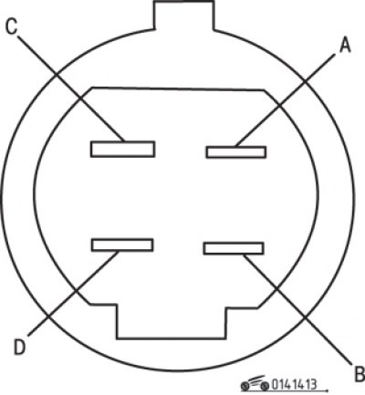
Figure 14.13. Location of contacts of the throttle position sensor connector of the EGR system
[Original version of the article on the website Mazbook]
Turn on the ignition and use a voltmeter to measure the voltage between each connector pin and "ground" (figure 14.13). The voltage at contact "A" should be 0.4-0.6 V, at contact "B" - less than 1.5 V, at contact "C" - 4.5-5.5 V and at contact "D" - less than 1.5 V.
Open the throttle fully and repeat the test. The voltage at contact "A" should be 4.5 V, at contact "D" - approximately 12 V. The voltage at contacts "B" and "C" should be the same as measured earlier.
If the voltage at terminal "D" does not correspond to the required value, check the adjustment of the throttle position sensor. If the voltage at other terminals does not match the required values, check the resistance of the throttle position sensor.
Turn off the ignition and install the rubber boot.
To adjust the throttle position sensor, disconnect the connector.
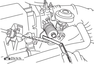
Figure 14.14. Using a feeler gauge to adjust the throttle position sensor of the EGR system
Insert a 0.2mm gap feeler gauge between the throttle lever and the adjusting screw, then use an ohmmeter to measure the continuity between terminals "D" and "B" on the sensor (figure 14.14). Insert a 0.5mm thick probe, the resistance between the contacts should be equal to infinity.
If necessary, adjust the position of the sensor to achieve the desired results.
Before connecting the connector, use an ohmmeter to measure the resistance between the connector contacts. With the throttle closed, the resistance between contacts "A" and "B" should be approximately 500 ohms, and with the throttle open, it should be approximately 4,500 ohms. Between contacts "B" and "C," the resistance should be between 4,000 and 6,000 ohms, regardless of throttle position; otherwise, replace the sensor.