
MazBook.ru
English Русский
Български
Беларускі
Український
Српски
Hrvatski
Română
Polski
Slovenský
Magyar
• Bookmark • Sitemap • Contacts •   
Cars Opel Cars Ford Cars Volkswagen Cars Audi Cars Kia Cars Renault Cars Peugeot


Familia Capella Mazda3 Mazda6 CX-? Others Articles
Capella 3 (1982-1992, petrol) Capella 3 and 4 (1982-1992) Capella 4 (1987-1992) Capella 5 (1991-1997) Capella 6 (1997-2005, petrol)

Fuel pump — inspection, removal and installation (since 1984) (Mazda Capella GC)

  • Home
  • Mazda Capella
  • Capella GC (1982-1992)
  • Power unit
  • Supply system
  • Fuel pump — inspection, removal and installation (since 1984)
0
Contents: Checking, removing and installing ⇓ Checking the fuel pump relay ⇓ Checking fuel pressure ⇓
The fuel pump is located at the lower rear of the vehicle next to the fuel tank. The fuel pump is of a centrifugal type, with five rollers moving planetarily inside a separator plate.

A diaphragm type damper at the fuel pump outlet reduces fuel pressure pulses generated by the pump rollers. The fuel pump is equipped with a valve designed to maintain residual pressure in the system when the engine is not running.

The fuel pump electrical circuit contains a switch mounted on the air flow meter that turns off the pump when the engine is stopped.

Checking, removing and installing


To check the pressure created by the fuel pump, you need a pressure gauge and a tube.

Disconnect the cable from the negative battery terminal.
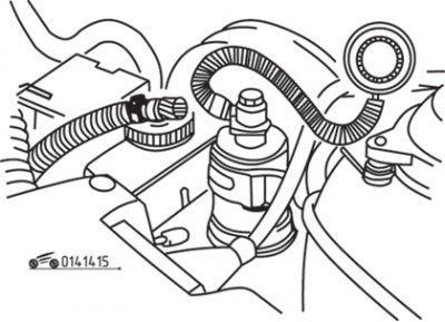
Figure 14.15. Checking the pressure generated by the fuel pump

Figure 14.15. Checking the pressure generated by the fuel pump


Disconnect the fuel hose from the engine side of the fuel filter and connect a pressure gauge in its place (figure 14.15).

Connect the cable to the negative terminal of the battery and turn on the ignition.


Figure 14.16. Using a piece of wire to connect the fuel pump test connector contacts

Figure 14.16. Using a piece of wire to connect the fuel pump test connector contacts


Using a piece of wire, connect the contacts of the fuel pump control connector together (figure 14.16) and check the fuel pressure, which should be within 3.5–5.0 kg/cm².

To check the fuel pump armature winding, block the front wheels, lift the rear of the vehicle and secure it on supports.

Disconnect the connector from the fuel pump and use an ohmmeter to measure the resistance between its contacts. If the resistance is 1.0 ohms, the fuel pump is good.

To remove the fuel pump, disconnect the inlet and outlet hoses and connector, then remove the bracket mounting bolts.

After removing the fuel pump, its operation can be checked by applying 12 V to the contacts of its connector.

Installation is carried out in the reverse order of removal.

Checking the fuel pump relay
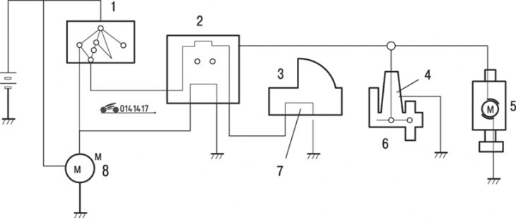


Figure 14.17. Connection diagram of the fuel pump power supply circuit opening relay: 1 – ignition…

Figure 14.17. Connection diagram of the fuel pump power supply circuit opening relay: 1 – ignition switch; 2 – circuit breaker relay; 3 – air flow meter; 4 – heating coil; 5 – fuel pump; 6 – air valve; 7 – fuel pump switch; 8 – starter


The circuit breaker relay, mounted on the right side of the bulkhead, supplies current to the fuel pump and air valve only when the engine is started and running (figure 14.17). After the engine stops, the circuit is opened by the fuel pump switch on the air flow meter.
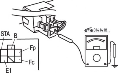
Figure 14.18. Fuel pump circuit breaker relay connector contact locations: Fp – to the fuel pump;…

Figure 14.18. Fuel pump circuit breaker relay connector contact locations: Fp – to the fuel pump; Fc – to the fuel pump switch; B – to the ignition switch; STA – to the ignition switch (ST); E1 – "mass"


With the ignition on, use a voltmeter to measure the voltage between the contacts on the relay (figure 14.18). The voltage between terminals "Fc" and "B" should be 12 V. Open the air flow meter measuring plate and make sure that the voltage between terminals "Fp" and "B" is 12 V.

Disconnect and connect to ground the ignition coil wire "HT", then ask an assistant to turn the key in the ignition switch to the engine start position and check that there is 12 V voltage between contacts "Fp", "B" and "STA".

Disconnect the connector from the relay and use an ohmmeter to measure the resistance between contacts "STA" and "E1", which should be within 15–30 Ohms, between contacts "B" and "Fc" – 80–150 Ohms, and between contacts "B" and "Fp" equal to infinity.


Replace the relay if necessary.

Checking fuel pressure


To check the pressure you need a pressure gauge, a tee and a tube.

Disconnect the cable from the negative battery terminal.

Disconnect the fuel hose from the engine side of the fuel filter and connect a pressure gauge in its place.

Connect the cable to the negative terminal of the battery and turn on the ignition.

Using a piece of wire, connect the contacts of the fuel pump control connector together (see figure 14.15) and check the fuel pressure, which should be 2.5–2.85 kg/cm².

Start the engine and let it idle, then check that the fuel pressure is between 1.9 and 2.3 kg/cm².

If the fuel pressure is not as specified, check the fuel filter, pump and pressure regulator.

Turn off the ignition, remove the connecting wire and pressure gauge, then reinstall the fuel hose.
This article is available at: russian, bulgarian, belarusian, ukrainian, serbian, croatian, romanian, polish, slovak, hungarian
This text was checked by: Georgy Afanasyev
Share with friends on social networks:

Previous
Capella 3 and 4 » Supply system
Next

Air valve (since 1984)
Throttle body — removal, inspection and installation (since 1984)
Distributed fuel injection system (since 1984)
Carburetor — removal, inspection and installation (since 1984)
Power supply system malfunctions, their causes and troubleshooting…
Fuel Injectors — checking, removing, and installing (since 1984)
Fuel pressure regulator (since 1984)
Control unit of the RVT system (since 1984)
Adjusting the accelerator cable of the RVT system (since 1984)
Checking the components of the electronic injection control system…
More articles on repairing other Mazda models
Fuel pump — removal and installation Mazda Familia 5 (1985-1989)
Checking for fuel leaks after installing the pump unit (diesel) Mazda3 BK (2003-2009)
Fuel Pump Unit — General Information Mazda6 GG (2002-2008)
Checking fuel injectors of the high-pressure fuel pump Mazda CX-5KE (2012-2017)
Removal and installation an additional fuel filter (on the… Mazda BT-50 (1) (2006-2011)
Link in different formats to this article
Comments and feedback from visitors
No comments yet


How much will 32 + 27 ?


Capella 6 (1997-2005, petrol) 
  • General information
  • Introduction to guide
  • User manual
  • Troubleshooting
  • Maintenance
  • Power unit
  • 4-cylinder engines
  • 6-cylinder engines
  • Engine overhaul
  • Cooling and ventilation
  • Power and exhaust systems
  • Engine electrics
  • Control system
  • Transmission
  • Mechanical gearbox
  • Automatic gearbox
  • Clutch and drive shafts
  • Chassis
  • Brake system
  • Car suspension
  • Steering
  • Body
  • Exterior (external elements)
  • Interior (internal elements)
  • Doors, windows and locks
  • Electrical equipment
  • Equipment and devices
  • Electrical circuits
Capella 5 (1991-1997) 
  • General information
  • User manual
  • Maintenance
  • Helpful hints
  • Power unit
  • Petrol engines 1.6 and 1.8
  • Petrol engines 2.0
  • 2.5 petrol engines
  • Overhaul engines 1.6 and 1.8
  • Overhaul engines 2.0 and 2.5
  • Diesel engine 2.0
  • Engine electrics
  • Cooling system
  • Air conditioner
  • Carburetor Nikki 30/34
  • Power system (1.6 and 1.8)
  • Power system (2.0 and 2.5)
  • Control system
  • Transmission
  • Mechanical gearbox
  • Automatic gearbox
  • Clutch and axles
  • Chassis
  • Brake system
  • Suspension and wheels
  • Steering
  • Body
  • Exterior (external elements)
  • Interior (internal elements)
  • Doors and windows
  • Electrical equipment
  • Equipment and devices
  • Electrical circuits
Capella 4 (1987-1992) 
  • General information
  • Introduction to manual
  • Vehicle specifications
  • Power unit
  • Engine repair
  • Lubrication system
  • Cooling system
  • Fuel system (carburetor)
  • Fuel injection (FE)
  • Fuel injection (DOHC)
  • Fuel system (diesel)
  • Ignition system
  • Transmission
  • Clutch
  • Gearbox
  • Drive shafts
  • Chassis
  • Front suspension
  • Rear suspension
  • Steering system
  • Brake system
  • Electrical equipment
  • Equipment and devices
  • Electrical circuits
Capella 3 and 4 (1982-1992) 
  • General information
  • User manual
  • Maintenance
  • Power unit
  • Gasoline engine
  • Engine overhaul (gasoline)
  • Diesel engine
  • Cooling and heating
  • Supply system
  • Ignition system
  • Emission reduction
  • Transmission
  • Clutch
  • Mechanical gearbox
  • Automatic gearbox
  • Drive shafts
  • Chassis
  • Brake system
  • Suspension and wheels
  • Steering
  • Body
  • Exterior (external elements)
  • Interior (internal elements)
  • Electrical equipment
  • Equipment and devices
  • Power devices
  • Electrical circuits
Capella 3 (1982-1992, petrol) 
  • General information
  • User manual
  • Maintenance
  • Troubleshooting
  • Late models
  • Power unit
  • Engine in car
  • Engine overhaul
  • Cooling and heating system
  • Fuel and exhaust system
  • Engine electrical system
  • Emission control system
  • Transmission
  • Mechanical gearbox
  • Automatic gearbox
  • Clutch and drive shafts
  • Chassis
  • Brake system
  • Suspension and wheels
  • Steering
  • Body
  • Exterior (external elements)
  • Interior (internal elements)
  • Electrical equipment
  • Equipment and devices
  • Lighting and lamps
  • Electrical circuits
MazBook.ru © 2018–2026 · Mobile version · Articles and news · Sitemap: EN BG BY UA RS HR RO PL SK HU · Feedback · Site search · Add to bookmarks Familia 5 (BF) · Familia 6 (BG) · Capella 3 (GC) · Capella 3 and 4 (GC) · Capella 4 (GD) · Capella 5 (GE) · Capella 6 (GF) · Mazda3 BK · Mazda6 GG · CX-5KE · Mazda 121 (3) · Mazda BT-50 (1) ·
By continuing to use the site, you agree to the use of cookies 🔐