
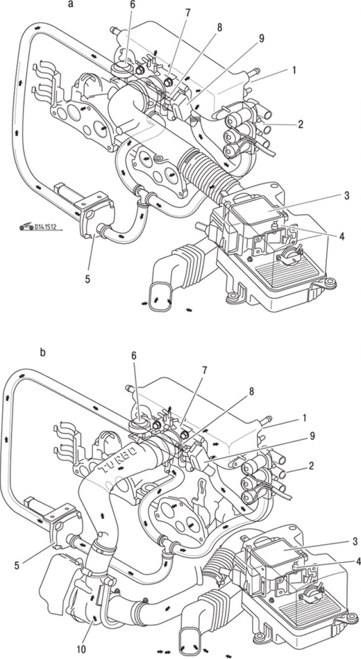
Pic. 15.12. Air supply system: a - engines without turbocharging; b - turbocharged engines; 1 – smoothing receiver; 2 - bypass solenoid valve; 3 - air flow meter; 4 - intake air temperature sensor; 5 - air valve; 6 - pneumatic shock absorber; 7 - throttle assembly; 8 - screw for adjusting the speed of the crankshaft of the engine at idle; 9 - throttle opening angle sensor; 10 - turbocharger
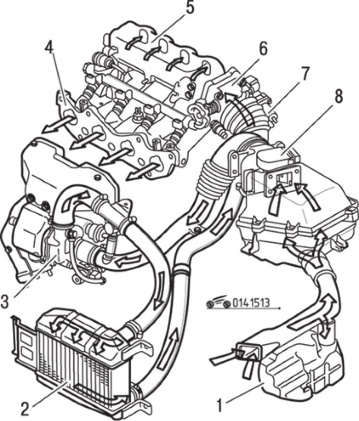
Pic. 15.13. Air supply system for turbocharged engines with intercooler: 1 - resonator; 2 - intermediate cooler; 3 - turbocharger; 4 - intake manifold; 5 – flow formation chamber; 6 - throttle assembly; 7 - valve of the bypass air channel; 8 - air flow meter
The air supply system consists of an air filter, an air flow meter and a throttle assembly. Automatic adjustment of the idle speed according to various engine operating conditions is provided by an auxiliary air valve combined with a bypass solenoid valve (pic. 15.12, 15.13). The air flow meter transmits information about the amount of air taken in by the engine to the control unit. The air flow and temperature at the nozzle inlet are measured using a compensator and a temperature sensor. Based on these measurements, the control unit determines the amount of fuel to be injected or the duration of the injection. The throttle position is set by the driver. As the throttle valve opens, the amount of air passing through the system increases, the compensator opens even more and the control unit generates a signal that controls the fuel supply system, the portion of injected fuel increases.