
MazBook.ru
English Русский
Български
Беларускі
Український
Српски
Hrvatski
Română
Polski
Slovenský
Magyar
• Bookmark • Sitemap • Contacts •   
Cars Opel Cars Ford Cars Volkswagen Cars Audi Cars Kia Cars Renault Cars Peugeot


Familia Capella Mazda3 Mazda6 CX-? Others Articles
Capella 3 (1982-1992, petrol) Capella 3 and 4 (1982-1992) Capella 4 (1987-1992) Capella 5 (1991-1997) Capella 6 (1997-2005, petrol)

Turbocharger — inspection, removal and installation (since 1986) (Mazda Capella GC)

  • Home
  • Mazda Capella
  • Capella GC (1982-1992)
  • Power unit
  • Supply system
  • Turbocharger — inspection, removal and installation (since 1986)
0
Contents: Checking the turbocharger ⇓ Removal and installation a…⇓
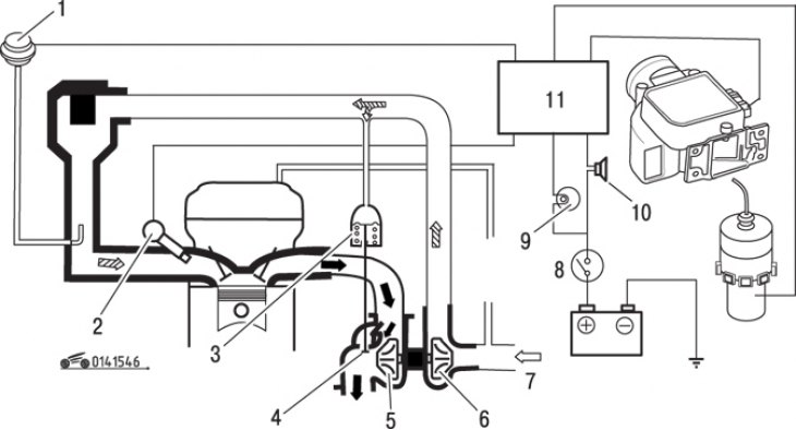
Figure 15.46. Turbocharging diagram: 1 – pressure sensor; 2 – nozzle; 3 – actuator; 4 – bypass…

Figure 15.46. Turbocharging diagram: 1 – pressure sensor; 2 – nozzle; 3 – actuator; 4 – bypass valve; 5 – turbine wheel; 6 – turbocharger; 7 – from the air flow meter; 8 – ignition switch; 9 – turbocharger indicator lamp; 10 – warning buzzer; 11 – control unit
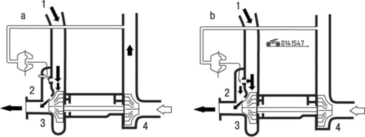

Figure 15.47. Turbocharger bypass valve operation diagram: a – the valve is closed; b – the valve…

Figure 15.47. Turbocharger bypass valve operation diagram: a – the valve is closed; b – the valve is open; 1 – exhaust gas flow; 2 – bypass valve; 3 – turbine wheel; 4 – turbocharger wheel


The turbocharging system is designed to boost the engine by increasing the pressure of the fuel-air mixture at the entrance to the combustion chamber using a turbocharger driven by the exhaust gas flow (figure 15.46). Turbocharging improves the filling of the cylinders with the fuel-air mixture. The air pressure in the intake manifold is controlled by a turbocharger wastegate valve combined with an actuator (the valve is actuated by a spring-loaded rod that moves under the influence of pressure on the intake manifold). The valve directs part of the exhaust gases past the turbine blades, thereby regulating the amount of air pumped in (figure 15.47). Later turbocharged models are fitted with an intercooler to cool the air entering the turbocharger (figure 15.47).


Checking the turbocharger


The design of a turbocharger is relatively simple, but this precision unit can easily fail if the oil or coolant supply is interrupted, or due to loose fastenings or mechanical damage to the pipelines. Diagnostics and maintenance of the unit are carried out according to specific methods using specialized equipment, therefore, to troubleshoot, you should contact an auto service center or specialized workshop. However, in a garage setting, you can check the integrity and correctness of the connections, as well as the tightness of the system, remove and install the turbocharger, thereby saving on the cost of replacement work.

Each turbocharger has its own characteristic noise produced during operation, so a change in the noise characteristic of this unit may be a sign of a malfunction. A high-pitched whistling sound may indicate a gas leak from the intake or exhaust manifold. If your turbocharger makes an unusual noise, take it to a car service center or a specialized workshop for repair. Check the exhaust manifold periodically for cracks or loose connections. With turbine speeds reaching up to 140,000 min⁻¹, a loss of coolant or contamination of the bearing oil can cause serious damage. Check the tightness of the lines supplying coolant and oil. A sign of a leak is traces of burnt oil on the turbocharger housing.

Important! When replacing engine bearings, such as main, connecting rod, or camshaft bearings, it is advisable to flush the turbocharger with clean engine oil.


Removal and installation a turbocharger


Drain the coolant from the cooled engine.

Remove the ignition distributor.
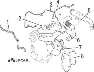
Figure 15.48. Turbocharging system elements: 1 – air tube; 2 – upper insulating casing; 3 – oil…

Figure 15.48. Turbocharging system elements: 1 – air tube; 2 – upper insulating casing; 3 – oil pipeline (to the turbocharger); 4 – secondary air tube; 5 – air intake and air hose; 6 – recirculation valve tube; 7 – oxygen concentration sensor; 8 – lower insulating casing


(Based on website data: MAZbook.ru)

Remove the air intake and air hose (figure 15.48).

Remove the air tube.

Remove the lower insulating casing.

Remove the secondary air supply tube.

Remove the oil line from the turbocharger.

Remove the upper insulating cover.

Disconnect the recirculation valve tube from the exhaust manifold.

Remove the coolant hoses.

Remove the oxygen concentration sensor from the exhaust manifold.

Remove the front exhaust pipe from the catalytic converter.

Loosen the bolts securing the turbocharger to the bracket.

Loosen the exhaust manifold mounting bolts and remove the turbocharger assembly with the exhaust manifold and front pipe.

Loosen the nuts securing the exhaust manifold and front pipe to the turbocharger.


Check the radial and axial clearances of the turbocharger rotor. If axial or radial play is felt, the turbocharger must be replaced.

Before installation, lubricate the turbocharger bearings by injecting 25 cm³ of engine oil into the turbocharger lubrication hole.

Attach the exhaust manifold and front pipe to the turbocharger. Replace the gaskets. Tighten the nuts to the specified torque.

Further installation is carried out in the reverse order of removal.

Before starting the engine, disconnect the wire from the negative terminal of the ignition coil. To increase oil pressure and fill the lubrication system, turn the engine crankshaft with the starter for 20 seconds. Connect the wire to the negative terminal of the ignition coil and start the engine. The engine crankshaft speed can be increased no earlier than 30 seconds after starting.
This article is available at: russian, bulgarian, belarusian, ukrainian, serbian, croatian, romanian, polish, slovak, hungarian
This text was checked by: Georgy Afanasyev
Share with friends on social networks:

Previous
Capella 3 and 4 » Supply system
Next

Checking, removing and installing electronic control system…
Idle Speed Compensation System (1986 and 1987)
Air shock absorber (since 1986)
Air supply system components (since 1986)
Fuel supply system components (since 1986)
More articles on repairing other Mazda models
Turbocharger — removal and installation Mazda Familia 5 (1985-1989)
Turbocharger — General Information Mazda BT-50 (1) (2006-2011)
Link in different formats to this article
Comments and feedback from visitors
No comments yet


How much will 26 + 25 ?


Capella 6 (1997-2005, petrol) 
  • General information
  • Introduction to guide
  • User manual
  • Troubleshooting
  • Maintenance
  • Power unit
  • 4-cylinder engines
  • 6-cylinder engines
  • Engine overhaul
  • Cooling and ventilation
  • Power and exhaust systems
  • Engine electrics
  • Control system
  • Transmission
  • Mechanical gearbox
  • Automatic gearbox
  • Clutch and drive shafts
  • Chassis
  • Brake system
  • Car suspension
  • Steering
  • Body
  • Exterior (external elements)
  • Interior (internal elements)
  • Doors, windows and locks
  • Electrical equipment
  • Equipment and devices
  • Electrical circuits
Capella 5 (1991-1997) 
  • General information
  • User manual
  • Maintenance
  • Helpful hints
  • Power unit
  • Petrol engines 1.6 and 1.8
  • Petrol engines 2.0
  • 2.5 petrol engines
  • Overhaul engines 1.6 and 1.8
  • Overhaul engines 2.0 and 2.5
  • Diesel engine 2.0
  • Engine electrics
  • Cooling system
  • Air conditioner
  • Carburetor Nikki 30/34
  • Power system (1.6 and 1.8)
  • Power system (2.0 and 2.5)
  • Control system
  • Transmission
  • Mechanical gearbox
  • Automatic gearbox
  • Clutch and axles
  • Chassis
  • Brake system
  • Suspension and wheels
  • Steering
  • Body
  • Exterior (external elements)
  • Interior (internal elements)
  • Doors and windows
  • Electrical equipment
  • Equipment and devices
  • Electrical circuits
Capella 4 (1987-1992) 
  • General information
  • Introduction to manual
  • Vehicle specifications
  • Power unit
  • Engine repair
  • Lubrication system
  • Cooling system
  • Fuel system (carburetor)
  • Fuel injection (FE)
  • Fuel injection (DOHC)
  • Fuel system (diesel)
  • Ignition system
  • Transmission
  • Clutch
  • Gearbox
  • Drive shafts
  • Chassis
  • Front suspension
  • Rear suspension
  • Steering system
  • Brake system
  • Electrical equipment
  • Equipment and devices
  • Electrical circuits
Capella 3 and 4 (1982-1992) 
  • General information
  • User manual
  • Maintenance
  • Power unit
  • Gasoline engine
  • Engine overhaul (gasoline)
  • Diesel engine
  • Cooling and heating
  • Supply system
  • Ignition system
  • Emission reduction
  • Transmission
  • Clutch
  • Mechanical gearbox
  • Automatic gearbox
  • Drive shafts
  • Chassis
  • Brake system
  • Suspension and wheels
  • Steering
  • Body
  • Exterior (external elements)
  • Interior (internal elements)
  • Electrical equipment
  • Equipment and devices
  • Power devices
  • Electrical circuits
Capella 3 (1982-1992, petrol) 
  • General information
  • User manual
  • Maintenance
  • Troubleshooting
  • Late models
  • Power unit
  • Engine in car
  • Engine overhaul
  • Cooling and heating system
  • Fuel and exhaust system
  • Engine electrical system
  • Emission control system
  • Transmission
  • Mechanical gearbox
  • Automatic gearbox
  • Clutch and drive shafts
  • Chassis
  • Brake system
  • Suspension and wheels
  • Steering
  • Body
  • Exterior (external elements)
  • Interior (internal elements)
  • Electrical equipment
  • Equipment and devices
  • Lighting and lamps
  • Electrical circuits
MazBook.ru © 2018–2026 · Mobile version · Articles and news · Sitemap: EN BG BY UA RS HR RO PL SK HU · Feedback · Site search · Add to bookmarks Familia 5 (BF) · Familia 6 (BG) · Capella 3 (GC) · Capella 3 and 4 (GC) · Capella 4 (GD) · Capella 5 (GE) · Capella 6 (GF) · Mazda3 BK · Mazda6 GG · CX-5KE · Mazda 121 (3) · Mazda BT-50 (1) ·
By continuing to use the site, you agree to the use of cookies 🔐