


Contents: 5.2.1. Float level ⇓ 5.2.2. Throttle valve opening ⇓ 5.2.3. High-speed idle ⇓ 5.2.4. Idle speed adjustment ⇓
5.2.1. Float level
The fuel level can be seen when the carburetor is installed, as a viewing glass is installed in the float chamber. To check, you need to start the engine and check whether the fuel is at the same height as the marking on the glass.
The float level must be controlled in a raised, vertical position. For the first check, you can use a piece of steel rod. For the second check, use a measuring ruler. Proceed as follows:
Remove the carburetor cover.
Turn the carburetor so that the float can lie flat, and measure the distance between the lower edge of the float and the surface of the carburetor cover. Use 12.5mm steel rod (eg twist drill) and insert it into the gap, as shown in the picture 130. Do not insert the lid seal. If necessary, adjust the tongue (A). Check the float level again. The steel rod also needs to be inserted and the float tilted to one side and the surface of the lid to the other.
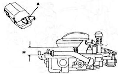
Figure 130. Checking the float level with the cover turned. Measure size H. Bend the tongue (A) of the float for adjustment.
For the second check, hold the float as shown in the figure 131, and measure the size "L" between the indicated points. If it is not equal to 44.0 mm, then the tongue of the float "B" in the figure must be bent accordingly.
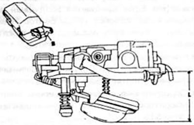
Figure 131. Checking the float level with the float hanging down. Measure size L, bend the float stop (B) for adjustment
5.2.2. Throttle valve opening
Place the carburetor upwards and open the first stage throttle valve, turning the lever to the left. Check that the throttle valve is exactly in the right corner relative to the hole.
If there is no failure, bend the throttle lever limiting tab.
Open the first stage throttle fully and with the other hand press the second stage throttle lever to the left. Check that the first stage throttle valve forms an angle of 45° if the second stage valve is also open. To measure this angle, you can insert a 7.3 to 8.3 mm drill bit at the location shown in the figure 132. If the gap does not match the size with the second stage damper open, bend the lever in the figure 133. until the gap reaches the desired size.
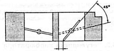
Figure 132. Adjusting the throttle opening. Insert a drill bit into the indicated location to check the first stage throttle valve hole.
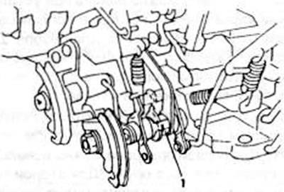
Figure 133. Bend the limiter (1) for adjusting the second stage throttle valve opening.
5.2.3. High-speed idle
- Close the air damper completely by turning the lever.
- Measure the clearance between the edge of the first stage throttle valve and the carburetor bore using a 1.40-1.76 mm drill bit, for a 1.6 liter engine or an engine running on unleaded gasoline. For a 2.0-liter engine, the size is 0.48-0.64 mm with a step gearbox or 0.56-0.72 mm with an automatic gearbox. In the last mentioned car, you need to warm up the carburetor for at least one hour longer at room temperature and then check that the average thrust of the stepped cam lever is equal to 25° - the marking of the stepped cam. If adjustment is necessary, observe the following:
- For a 1.6-liter engine or an engine running on unleaded gasoline, bend the lever shown in the figure 134. and correct the gap.
- For another engine, adjust the one shown in the figure 135 bolt to correct the gap.
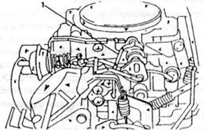
Figure 134. Adjusting the idle speed (fast idle). Bend the levers (1) for adjustment.
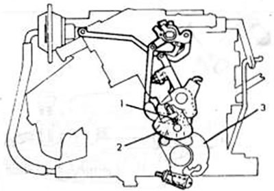
Figure 135. Details of idle speed adjustment (see text). 1. Adjusting bolt; 2. Step cam lever; 3. Throttle lever
5.2.4. Idle speed adjustment
Idle speed and CO content in the fuel mixture must be set simultaneously. You need to have a rev counter and a CO meter, but below is a method that can be used without using these devices.
All current collectors must be switched off, and the fan must not be running. To do this, you need to pull out the black plug, which interrupts the electrical circuit. If the automatic transmission is installed, move the control lever to the "N" position. Proceed as follows:
- Connect the speed meter and CO content meter in accordance with the manufacturer's instructions.
- Start the engine and let it warm up.
- For vehicles with exhaust gas regulation, remove the hoses from the exhaust valves and plug the ends.
- Check the air damper for free movement.
- Remove the sealed plug on the side of the throttle body using the idle air mixture adjustment screw, unscrew the screw completely with the appropriate force and in this position make 3 turns inward. The position of the screw is shown in the figure 136.
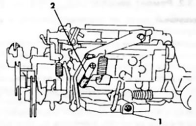
Figure 136. Location of the idle speed adjustment screw (1) and the fuel mixture adjustment screw (2)
Idle speed should be adjusted under the following conditions:
- Adjust the bolt (2) in Figure 136 until the engine produces 800 rpm with the stepped gearbox installed, 950±50 rpm with the built-in automatic gearbox for a 1.6-liter engine, or 900±50 rpm for a 2.0-liter engine
- An engine running on unleaded fuel should produce 850 rpm.
- Speed up the engine and check the idle speed again. If necessary, make further adjustments.
- Check the CO content in the exhaust gases using a CO meter. To do this, run the engine at 2000 rpm for 30 seconds, wait 1 minute, and then read the reading. This task must be completed within 3 minutes.
- If the CO content is not within 2.0%±0.5%, then adjust the fuel mixture composition adjustment screw (1) in Figure 136 step by step until it is. until the desired reading is obtained.
- After adjustment, reconnect the air hoses (if any) and insert a new sealed plug into the hole for the adjusting screw. If there is no CO meter, then you need to move the mixture control screw until the engine rotates at maximum speed and then turn the adjusting screw until the engine rotates slightly faster than the specified speed for this type of engine. As soon as a failure occurs, unscrew the mixture control screw until the engine again reaches the prescribed speed. The adjustment should be seen as a temporary measure only. i.e. as an auxiliary measure and checked with appropriate devices.
Instructions: Under normal conditions, it should be sufficient if the idle speed is adjusted by the throttle valve bolt.