


11.1.1. For a gasoline engine
The gearbox can be removed with the engine installed. To lift the gearbox you need to have a jack at your disposal. Carry out the following work:
- Disconnect the battery cable and remove the battery completely.
- For a pump-carburetor engine, unscrew the main fuse block on the wall on the left after the individual plugs have been removed, and remove the block.
- Remove the wire from the wall of the ignition distributor.
- Remove the air filter.
- For a pump-carburetor engine, disconnect the air outlet hose from the large air hose and remove the inlet hose after releasing the clamp.
- Disconnect the battery cable from the top of the transmission. DOHC vehicles with ABS have an additional wire attached next to the line for the clutch master cylinder line. A carburetor engine has only one wire.
- On the gearbox axle shaft, loosen the nut with the oblique mesh knurling from the bottom side of the tachometer spiral and pull the spiral upwards. Move the coil to the side so that it does not interfere.
- Unscrew the clutch head cylinder, release the hose clamps and, hanging the cylinder on the hose, secure it with a piece of wire. Do not open hydraulic connections of pipelines.
- Disconnect the hose from the evaporative tank.
- Remove the four bolts on the top side between the engine and gearbox.
- Place the front of the car on jack stands.
- Place a rope or chain through the engine lugs and hang it on the hoist, then lift the engine until it is under tension.
- Place a suitable container under the gearbox and unscrew the drain plug on the bottom side. The gearbox contains approx. 3.5 liters of oil, and the container must have the appropriate volume.
- Disconnect the plug connections of the electrical wires of the gearbox. Depending on the engine type, up to three plugs are disconnected.
- Disconnect the wire from the starter terminals and remove the starter.
- Unscrew both front wheels.
- Remove the mudguard from the left wheel arch.
- Release the anti-roll bar connecting links on the wishbone and separate the ball joints of the wishbone as described in the "Front Wheel Suspension" chapter. Perform this work on both sides of the vehicle.
- Disengage the left drive shaft from the gearbox as follows:
— Insert a tire fitting tool between the drive shaft joint and the gearbox housing as shown in the figure 166. Hit the end of the lever until the shaft disengages from the differential axle gear. Make sure that the oil seal ring is not damaged. Hold the constant velocity joint with one hand on the inside as shown in the figure 167, and pull the entire drive axle gearbox outward until the end of the drive shaft is completely out of the gearbox.
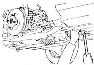
Figure 166. Knocking out the constant velocity joint of the left drive shaft
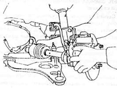
Figure 167. Removing the left drive shaft from the gearbox
- Remove the right drive shaft and constant velocity joint from the gearbox as follows:
— Insert a tire iron between the drive shaft and the constant velocity joint as shown in Figure 168 and strike with a hammer until the shaft disengages.
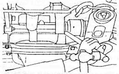
Figure 168. Removing the right drive shaft and connecting shaft.
— Loosen the bolts securing the propeller shaft to the thrust bearing and remove the entire shaft from the gearbox.
- Except for the DOHC engine, remove both arc-shaped supports on the right side of the transmission.
One of them is located in front and the other one is located in the back.
- Except for the DOHC engine, unscrew the protective sheet under the clutch housing.
- Loosen the nuts on the underside of the gearbox suspension eyelet on the vehicle's crossmember, and lower the entire crossmember together with the left wishbone to the floor. Make sure that the crossmember is securely supported from below before unscrewing the last nut. Also remove the rubber-metal suspension on the crossmember.
- Unscrew the gearbox mount on the left side and also disconnect the mount earring from the gearbox. At the front, on the other side of the gearbox, disconnect the suspension.
- Using the drawing 169, unscrew the gear shift fork rod from the switch shaft in the gearbox and the stabilizer rod from the switch on the wall of the gearbox.
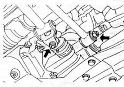
Figure 169. Removing the shift fork rod (words) and the shift stabilizer rod (right)
- Place a jack under the gearbox and lift it slightly.
- Loosen the bolts on the underside between the engine and gearbox and carefully place the gearbox on the jack to the side. Another person must operate the jack. because the gearbox must be securely held during removal. At the same time, make sure that the weight of the gearbox does not press on the clutch shaft, as the driven disk may be bent or damaged.
- If necessary, unscrew the suspension earring and rubber support from the gearbox. The gearbox is installed in reverse order, observing the following points:
- Check that the engine hangs securely on the chain or cable and can be lifted easily.
- Place the gearbox on a jack and tighten the jack. In this case, you need to hold the gearbox well and press it against the engine. The jack should be raised or lowered until the clutch shaft and driven disc are in line. Press the gearbox firmly against the engine and insert both lower bolts if the gap is completely closed. After this, insert the remaining bolts and tighten to 90-118 Nm.
- Install the engine mount bracket. For this purpose, the one shown in the figure Install the 170 bracket in the gearbox and tighten the three bolts to 56-80 Nm. When viewed from the front, the bracket is on the right side.
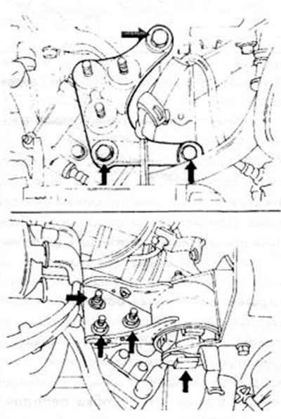
Figure 170. Fastening the suspension bracket in the upper figure (tightening torque 55-80 Nm) and the transmission mounts in the lower picture (see tightening torques. text).
- Place the pendant earring on the top side of the newly installed bracket. The three shown in the picture 170 nuts (A) tighten to 65-90 Nm, bolts inserted from the sides (B) – to 67-93 Nm.
- Mount the suspension on the gearbox from the drive side. Tighten the bolts on the box to 67-93 Nm.
- Reconnect the shift fork rod and the stabilizer rod in accordance with Figure 169.
- Place the crossmember together with the left transverse suspension arm in its position on three studs and lightly tighten the nuts. Insert three bolts on the right side (if you look from behind) and tighten the nuts and bolts as follows:
— Three bolts with a tightening torque of 46-55 Nm.
— Nuts on the front side — with a tightening torque of 75-95 Nm.
- Replace the thrust rings on the ends of the drive and cardan shafts. Insert the right shaft into the gearbox and then screw the shaft supports onto the gearbox. Tighten the fitting bolts to 7-10 Nm, other bolts to 43-62 Nm.
- Pull the steering knuckle outward and connect the drive shaft to the cardan shaft. After this, grab the axle joint and push it firmly inward until it snaps onto the driveshaft. Pull the steering knuckle outward again to check that the drive shaft is engaged properly. Be careful not to damage the oil seal ring.
- Insert the left drive shaft so that the inner end of the shaft enters the gearbox (first, pull the steering knuckle outward), and the constant velocity joint is pressed firmly against the gearbox. At the same time, make sure that the sealing ring in the gearbox is not damaged. Check that the shaft engages as described above for the right shaft.
- Connect the ball joint of the control arm to the steering knuckle, and tighten the nuts and bolts to 44-44 Nm. Screw the lower mudguard back on after installation (except DOHC engine). Do the same with the mudguard in the wheel arch.
- Reconnect the anti-roll bar arms. Tighten the top nuts until the threaded ends of the arms protrude 20.1 mm from the nuts.
- Screw on the wheels, lower the car to the floor and tighten the bolts to 90-120 Nm.
- Screw on the clutch cylinder.
- Fill the gearbox with oil (3.5 l - by opening the tachospiral) and carry out all other work in the reverse order of removal.
[Data provided by the website www.MazBook.ru]
11.1.2. For a diesel engine
- Disconnect the battery cable and remove the battery completely. Unscrew the battery bracket and remove it.
- Remove the supplied air filter.
- Unscrew the hood from the inside of the radiator and carefully remove the hood together with the fan. Before doing this, disconnect the fan motor plug.
- Unscrew the wire on the top side of the gearbox connecting the gearbox housing to the battery. Another additional wire is screwed to the front of the gearbox.
- On the gearbox axle shaft, loosen the nut with the oblique mesh knurling from the bottom side of the tachospiral, and pull the spiral upwards. Move the coil to the side so that it does not interfere.
- Unscrew the clutch head cylinder, release the hose clamps and, hanging the cylinder on the hose, secure it with a piece of wire. Do not open hydraulic connections of pipelines.
- Disconnect the pressure hose and the drain hose from the servo control.
- Remove the four bolts on the top side between the engine and gearbox.
- Place the front of the car on jack stands.
- Remove the mudguard from the left wheel arch.
- Disconnect the stabilizer bar connecting rods from the lower control arm and remove the control arm's pyrite pivot joints, as described in the "Front Wheel Suspension" chapter. Perform this work on both sides of the vehicle. Disengage the left and right drive shafts from the gearbox as described for the petrol engine.
- Remove both arch supports on the right side of the transmission. One of them is located in front and the other one is located in the back.
- Unscrew the protective sheet under the clutch housing.
- Loosen the nuts of the gearbox suspension eyelet on the vehicle's crossmember on the underside of the gearbox and lower the entire crossmember together with the left wishbone to the floor. Make sure that the crossbar is securely supported from below before the last nut is unscrewed.
- Unscrew the exhaust pipe arch support from the gearbox.
- Unscrew the gearbox mount on the left side and also disconnect the suspension earring from the gearbox. In front on the other side, disconnect the suspension.
- Using Figure 169, unscrew the gear shift fork rod from the switch shaft in the gearbox and the stabilizer rod from the switch on the wall of the gearbox.
- Place a jack under the gearbox and lift it slightly.
- Loosen the bolts on the underside between the engine and gearbox and carefully place the gearbox on the jack to the side. Another person must operate the jack as the transmission must be securely supported during removal. At the same time, make sure that the weight of the gearbox does not press on the clutch shaft. the driven disk may be bent or damaged.
- If necessary, unscrew the suspension earring and rubber support from the gearbox.
- The gearbox is installed in the reverse order of removal. The instructions given in chapter 11.1.1 for a petrol engine also apply to a diesel engine.