MazBook.ru
English Русский
Български
Беларускі
Український
Српски
Hrvatski
Română
Polski
Slovenský
Magyar
• Bookmark • Sitemap • Contacts •   
Cars Opel Cars Ford Cars Volkswagen Cars Audi Cars Kia Cars Renault Cars Peugeot


Familia Capella Mazda3 Mazda6 CX-? Others Articles
Capella 3 (1982-1992, petrol) Capella 3 and 4 (1982-1992) Capella 4 (1987-1992) Capella 5 (1991-1997) Capella 6 (1997-2005, petrol)

Rear Window Defogger — inspection and repair (Mazda Capella GF)

  • Home
  • Mazda Capella
  • Capella GF (1997-2005)
  • Electrical equipment
  • Equipment and devices
  • Rear Window Defogger — inspection and repair
0
Contents: Examination ⇓ Repair ⇓
1. The rear window defroster consists of horizontal heating elements glued to the inside of the rear window. Voltage is supplied to the heater through a fuse installed in the distribution box located in the engine compartment. The heater is activated by a switch located on the instrument panel.

2. Minor damage to the heating elements can be repaired without removing the rear window.

Examination


3. Turn on the ignition, then turn on the rear window defroster.

4. Connect a voltmeter to the positive and negative terminals of the heater. If the voltmeter does not show battery voltage, check the fuse, switch, heater relay, and associated wiring. If voltage is present, but all (or some) of the heating elements do not work, try the following:.

5. When measuring voltage in the following tests, wrap the voltmeter probe with aluminum foil and press the foil with your finger to the heating element (figure 22.5). Connect the negative probe of the voltmeter to the negative terminal of the heater.
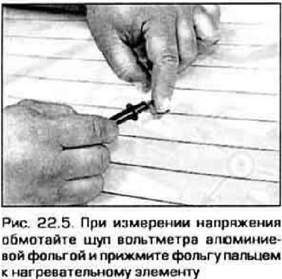
5. When measuring voltage in the following tests, wrap the voltmeter probe with aluminum foil and…


6. Measure the voltage at the center of each heating element (figure 22.6). If the voltage is 5-6 V, then the corresponding element is working properly (that is, it has no gaps). If the voltage is 0, then there is a break between the center of the corresponding element and the positive terminal of the heater. If the voltage is 1-12 V, then there is a break between the center of the element and the negative terminal of the heater. Check each heating element.
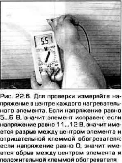


6. Measure the voltage at the center of each heating element (figure 22.6). If the voltage is 5-6…


7. If all components are in good condition, connect the negative probe of the voltmeter to the vehicle ground. The voltmeter reading should remain the same. If the voltmeter reading changes, it is necessary to restore the heater's contact with the ground.

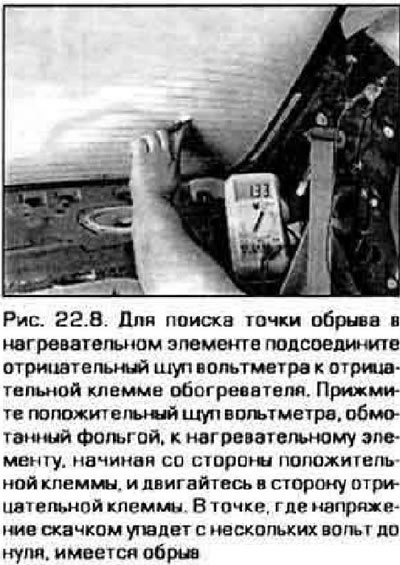
8. To find the open point in the heating element, connect the negative probe of the voltmeter to the negative terminal of the heater. Place the foil-wrapped positive probe of the voltmeter onto the heating element, starting at the positive terminal and moving toward the negative terminal. At the point where the voltage suddenly drops from a few volts to zero, there is a break (figure 22.8).

8. To find the open point in the heating element, connect the negative probe of the voltmeter to…


Original version of the article on the website: mazbook


Repair


9. To repair breaks, you can use a repair kit (for example, Dupont paste kit #4917, or similar). The kit contains a special conductive adhesive.

10. Before starting repairs, turn off the rear window defroster and let it cool for a few minutes.

11. Clean the area around the heating element with a fine wire brush, then wipe the area with methyl alcohol.

12. Apply adhesive tape around the area of the heating element to be repaired.

13. Thoroughly mix the epoxy adhesive from the repair kit according to the manufacturer's instructions.

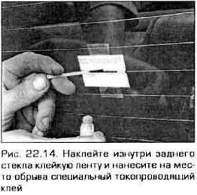
14. Apply glue to the break point and 2 cm of the heating element on each side of the break point (figure 22.14).

14. Apply glue to the break point and 2 cm of the heating element on each side of the break point…


15. Allow the mixture to dry for 24 hours, then remove the adhesive tape.
This article is available at: russian, bulgarian, belarusian, ukrainian, serbian, croatian, romanian, polish, slovak, hungarian
This text was checked by: German Vorobyov
Share with friends on social networks:

Previous
Capella 6 » Equipment and devices
Next

Daytime Running Light System — basic information
Sound signals — checking and replacement
Lamps — replacement
Headlight Actuators (Probe Model Only) — inspection and replacement
Headlights — replacement
Cruise control system — description, testing and adjustment of the…
Electric window system — description and testing
Central door locking system and remote control system
Electrically powered mirrors — description and testing
Electric Sunroof — description and testing
More articles on repairing other Mazda models
D. Wiring diagram for windshield wiper and washer, rear window... Mazda Familia 5 (1985-1989)
Rear window wiper (hatchback vehicles) Mazda3 BK (2003-2009)
Rear window cleaner Mazda6 GG (2002-2008)
Rear window wiper and washer (some versions) Mazda CX-5KE (2012-2017)
Scheme 21. Rear window wiper and washer Mazda 121 (3) (1996-2003)
Link in different formats to this article
Comments and feedback from visitors
No comments yet


How much will 40 + 41 ?


Capella 6 (1997-2005, petrol) 
  • General information
  • Introduction to guide
  • User manual
  • Troubleshooting
  • Maintenance
  • Power unit
  • 4-cylinder engines
  • 6-cylinder engines
  • Engine overhaul
  • Cooling and ventilation
  • Power and exhaust systems
  • Engine electrics
  • Control system
  • Transmission
  • Mechanical gearbox
  • Automatic gearbox
  • Clutch and drive shafts
  • Chassis
  • Brake system
  • Car suspension
  • Steering
  • Body
  • Exterior (external elements)
  • Interior (internal elements)
  • Doors, windows and locks
  • Electrical equipment
  • Equipment and devices
  • Electrical circuits
Capella 5 (1991-1997) 
  • General information
  • User manual
  • Maintenance
  • Helpful hints
  • Power unit
  • Petrol engines 1.6 and 1.8
  • Petrol engines 2.0
  • 2.5 petrol engines
  • Overhaul engines 1.6 and 1.8
  • Overhaul engines 2.0 and 2.5
  • Diesel engine 2.0
  • Engine electrics
  • Cooling system
  • Air conditioner
  • Carburetor Nikki 30/34
  • Power system (1.6 and 1.8)
  • Power system (2.0 and 2.5)
  • Control system
  • Transmission
  • Mechanical gearbox
  • Automatic gearbox
  • Clutch and axles
  • Chassis
  • Brake system
  • Suspension and wheels
  • Steering
  • Body
  • Exterior (external elements)
  • Interior (internal elements)
  • Doors and windows
  • Electrical equipment
  • Equipment and devices
  • Electrical circuits
Capella 4 (1987-1992) 
  • General information
  • Introduction to manual
  • Vehicle specifications
  • Power unit
  • Engine repair
  • Lubrication system
  • Cooling system
  • Fuel system (carburetor)
  • Fuel injection (FE)
  • Fuel injection (DOHC)
  • Fuel system (diesel)
  • Ignition system
  • Transmission
  • Clutch
  • Gearbox
  • Drive shafts
  • Chassis
  • Front suspension
  • Rear suspension
  • Steering system
  • Brake system
  • Electrical equipment
  • Equipment and devices
  • Electrical circuits
Capella 3 and 4 (1982-1992) 
  • General information
  • User manual
  • Maintenance
  • Power unit
  • Gasoline engine
  • Engine overhaul (gasoline)
  • Diesel engine
  • Cooling and heating
  • Supply system
  • Ignition system
  • Emission reduction
  • Transmission
  • Clutch
  • Mechanical gearbox
  • Automatic gearbox
  • Drive shafts
  • Chassis
  • Brake system
  • Suspension and wheels
  • Steering
  • Body
  • Exterior (external elements)
  • Interior (internal elements)
  • Electrical equipment
  • Equipment and devices
  • Power devices
  • Electrical circuits
Capella 3 (1982-1992, petrol) 
  • General information
  • User manual
  • Maintenance
  • Troubleshooting
  • Late models
  • Power unit
  • Engine in car
  • Engine overhaul
  • Cooling and heating system
  • Fuel and exhaust system
  • Engine electrical system
  • Emission control system
  • Transmission
  • Mechanical gearbox
  • Automatic gearbox
  • Clutch and drive shafts
  • Chassis
  • Brake system
  • Suspension and wheels
  • Steering
  • Body
  • Exterior (external elements)
  • Interior (internal elements)
  • Electrical equipment
  • Equipment and devices
  • Lighting and lamps
  • Electrical circuits
MazBook.ru © 2018–2026 · Mobile version · Articles and news · Sitemap: EN BG BY UA RS HR RO PL SK HU · Feedback · Site search · Add to bookmarks Familia 5 (BF) · Familia 6 (BG) · Capella 3 (GC) · Capella 3 and 4 (GC) · Capella 4 (GD) · Capella 5 (GE) · Capella 6 (GF) · Mazda3 BK · Mazda6 GG · CX-5KE · Mazda 121 (3) · Mazda BT-50 (1) ·
By continuing to use the site, you agree to the use of cookies 🔐