


2. Locate and check the system fuse (see paragraph 3).
3. The brake light switch disengages the cruise control system. Ask an assistant to press the brake pedal and make sure this is done. that the brake lights come on.
4. If the brake light bulbs do not light up, correct the problem.
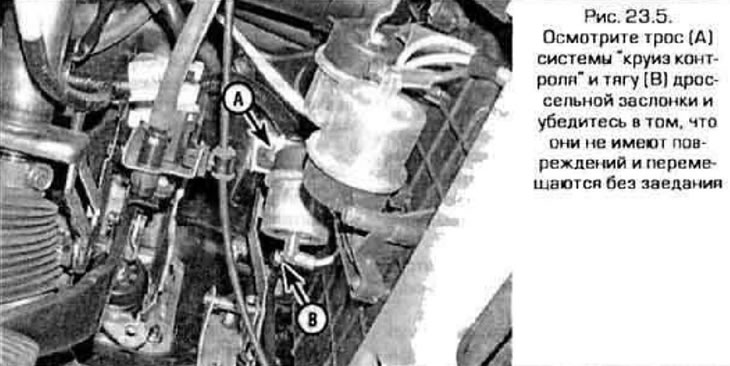
5. Inspect the cable connecting the actuator of the system to the throttle valve and adjust it (or replace) his (figure 23.5).
Data provided by the website MazBook
6. The cruise control system has a speed sensor installed in the vehicle's transmission. Checking the speed sensor is described in Chapter 6.
7. Take the vehicle for a test drive to ensure the system is working properly. If the system still does not work, contact a specialized service station.
"Cruise control" switches
Probe model
Examination
8. On the Probe model, the Set/Resume and On/Off switches are mounted on the steering wheel.
9. The procedure for removing the switches is described below.
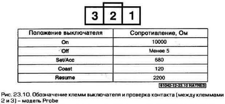
10. Using an ohmmeter and the appropriate wiring diagram, check that there is contact between the switch terminals in each position (figure 23.10). If at least one contact between the switch terminals is missing, replace the switch. If the switches are working properly, but the system does not turn on, check the wiring between the switch and the control unit.
Note: The vehicles described in this manual are equipped with two types of cruise control systems: electrically operated or vacuum-operated.
Replacement
11. Disable the airbag system (see paragraph 28).
12. Remove the driver's airbag unit from the steering wheel (see chapter 10).
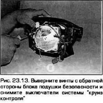
13. Remove the screws securing the switch (figure 23.13). Disconnect the connectors and remove the switches from the steering column.
14. Installation is carried out in the reverse order of removal.
Mazda model
Examination
15. In the Mazda model, the cruise control switch is not mounted on the steering wheel, however, the main switch for the cruise control system is mounted on the instrument panel.
16. The cruise control system has a built-in self-diagnostic function that tests all circuits except the Resume/Accel switch circuit. If this switch is faulty, contact a qualified service station.
17. To enable diagnostic mode, turn on the ignition (without starting the engine) and press the cruise control system activation button located on the dashboard. Press and hold the Resume/Accel button for 3 seconds.
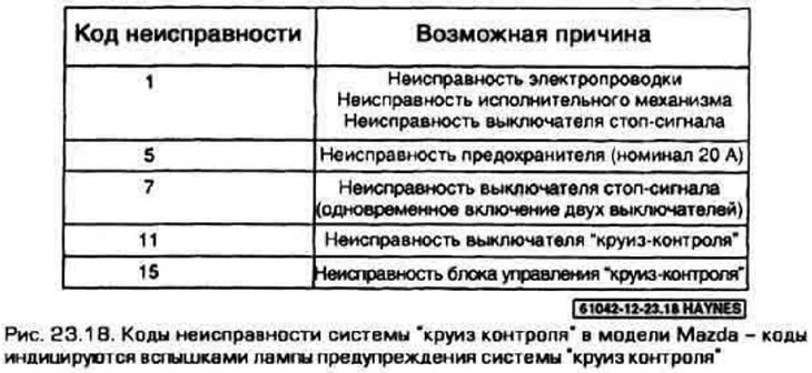
18. The cruise control warning light located on the instrument panel should come on for 3 seconds, then go out for 2 seconds, and then flash a series of times to display a fault code (if there is one) (figure 23.18). Count the number of lamp flashes. If there are multiple fault codes stored in the system, the fault code with the highest priority will be issued. Once the cause of the malfunction has been eliminated, the system will display the following error code.
19. The diagnostic mode is switched off by disabling the "cruise control" system (button located on the dashboard) or by turning the ignition key to the Lock position.
20. To check the system switch, you must first remove it (see below).
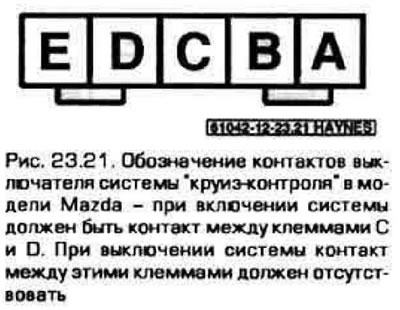
21. Using an ohmmeter and the appropriate wiring diagrams, check the contact between the switch terminals in each position (figure 23.21). If there is no contact between the switch terminals in at least one position, replace the switch.
Replacement
22. Remove the switches mounted on the steering wheel (see paragraphs 11-16). To remove the main system switch, pry it out of the dashboard using a screwdriver.
Note: To prevent damage to the instrument panel trim, wrap the screwdriver with electrical tape.
23. Disconnect the connector and remove the switch from the vehicle.
24. Installation is carried out in sequence. reverse of removal.
Adjusting the cable
25. Using pliers, remove the retainer from the cable at the point of attachment to the actuator in the engine compartment (figure 23.25).
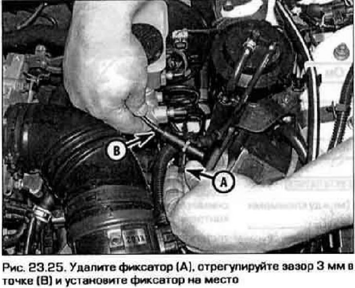
26. Pull the cable towards the actuator, observing the throttle linkage. Pull the cable until the free play of the cable is selected, now release the cable so that a free play of 3 mm is formed and install the lock in place.