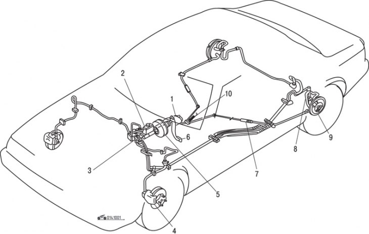
Pic. 10.1. The location of the elements of the brake system on the car: 1 – parking brake lever; 2 – the main brake cylinder; 3 - brake fluid pressure distributor; 4 - disc brake mechanism of the front wheel; 5 - vacuum brake booster; 6 – brake pedal; 7 - rear parking brake cable; 8 – brake pipes; 9 - drum brake mechanism of the rear wheel; 10 - front parking brake cable
The front brakes are ventilated disc, rear - drum. The service brake system regulates the speed of the vehicle and ensures that it stops with the necessary efficiency (pic. 10.1).
Tightening torques, Nm
| Brake pedal to bracket | 20–35 |
| Caliper mounting bolts: | |
| - top | 16–25 |
| - bottom | 20–30 |
| Bolts of fastening of a rotary fist | 50–76 |
| Brake hose to caliper: | |
| - front | 22–26 |
| - rear | 23–35 |
| Bolts of fastening of the working brake cylinder | 10–15 |
| Bolts of fastening of a back axis to a basic plate | 69 |
| Nuts of fastening of brake pipes | 13–22 |
| Wheel nuts | 90–120 |
The parking system keeps the vehicle stationary relative to the road. It is mainly used to hold a stationary car, but it can also be used when the working brake system fails.
All vehicles described in this manual are equipped with a hydraulic braking system. All brakes are equipped with automatic brake pad clearance adjustment. For front disc brakes, pad wear is compensated automatically, for the rear drum brake there is a mechanism for adjusting the gap of the pads up to a decrease in the thickness of the drum brake lining to 2.0 mm. The mechanism is activated every time the brake system is applied.
The hydraulic system consists of two separate circuits. The master brake cylinder is equipped with separate reservoirs for the two circuits, and in the event of a fluid leak or damage in one of the hydraulic actuators, the other remains operational. A dual pressure regulator distributes hydraulic pressure between the front and rear brake systems to prevent the rear wheels from locking up. An insufficient level of brake fluid in the hydraulic actuator is warned by a warning lamp activated by a sensor in the reservoir of the main brake cylinder.
The parking brake mechanically engages only the rear brakes. It is activated by lifting the lever located on the center console between the front seats.
The operation of the vacuum brake booster, located in the engine compartment on the bulkhead, is based on the use of intake manifold vacuum and atmospheric air pressure. After completing any operation involving the removal of any component of the brake system, always perform a test drive to check the operation of the vehicle's brakes before continuing its normal operation. Check the brakes while driving on a level, clean and dry road. Other test conditions may lead to inaccurate results. Test the brakes at various speeds under both low and high loads. The car should stop evenly, without pulling to the side. Avoid locking up the brakes as this will damage the tires and reduce braking efficiency and control.
Tire condition, vehicle loading, and front wheel alignment also affect brake performance.
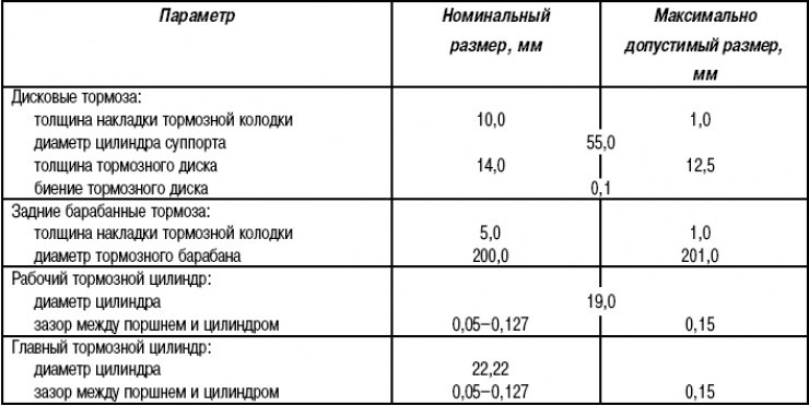
Technical data