


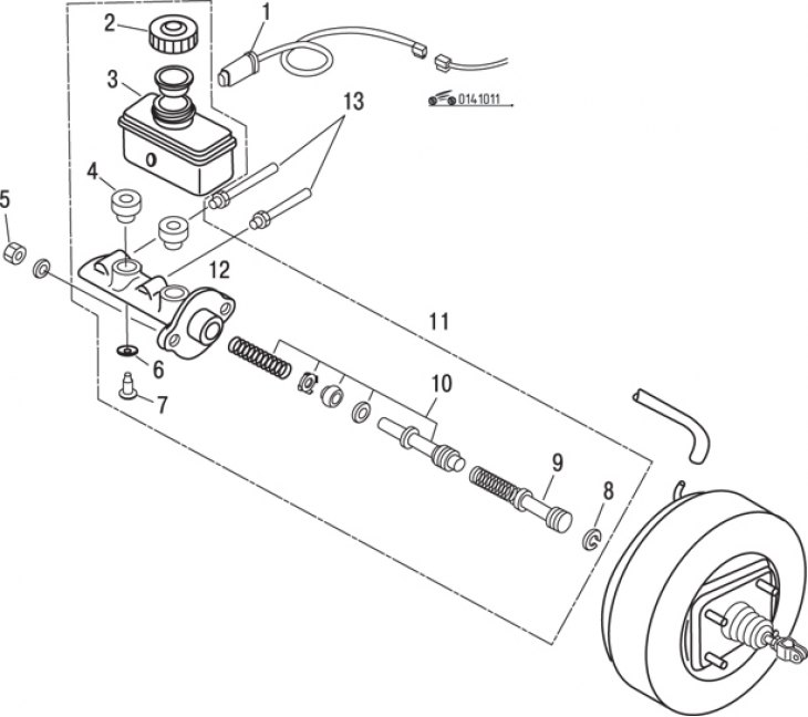
Figure 10.11. Master brake cylinder: 1 – brake fluid level sensor; 2 – tank lid; 3 – brake fluid reservoir; 4 – bushing; 5 – nut; 6 – O-ring seal; 7 – locking screw; 8 – thrust ring; 9 – primary piston assembly; 10 – secondary piston assembly; 11 – assembly of the master brake cylinder; 12 – master brake cylinder; 13 – brake pipes
Removal
Disconnect the brake lines from the master cylinder. To collect leaking fluid, place a rag or newspaper under the master cylinder. Disconnect the connector from the brake fluid level sensor, unscrew the two nuts securing the brake master cylinder and remove the brake master cylinder from the vehicle (figure 10.11).
Drain any remaining brake fluid from the reservoir. Remove the reservoir by holding the master cylinder firmly and rocking the reservoir from side to side.
Place the master cylinder in a vertical position (the front part should be facing down), press the primary piston and remove the thrust ring.
Remove the primary piston. The repair kit includes a replacement part.
Use a wooden stick to press down on the secondary piston, remove the O-ring and remove the screw.
Tap the master cylinder on a block of wood to remove the secondary piston.
Remove the spring from the front of the secondary piston.
Remove the rear spacer and cylinder cup seal, valve gaskets and two seals from the rear of the piston from the secondary piston.
Remove the tank bushings, cover and float.
Clean the master cylinder and inspect the bore for corrosion or damage. If significant signs of corrosion or damage are found, replace the master cylinder housing.
Inspect the tank for cracks and the bushings for wear, replacing them with new ones if necessary.
Before assembly, lubricate all components with clean brake fluid.
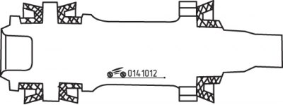
Figure 10.12. Location of seals on the secondary piston of the master brake cylinder
Install the valve gasket in front of the secondary piston. Place the seal on the piston (open part forward) (figure 10.12).
Install the center seal onto the secondary piston with the open end facing forward.
Install the secondary piston rear seal with the open side facing the rear.
Install the O-ring onto the secondary piston mounting screw.
Repair
Purchase a brake master cylinder repair kit.
Unscrew the air bleed nipple and shake out the steel ball. If necessary, tap the wheel cylinder against a wooden block to remove the ball.
Caution! Avoid allowing brake fluid to come into contact with your vehicle's paintwork, as it may damage it.
Remove the dust boots and pistons from the cylinder bore, then separate the boots from the pistons.
Press the piston on one side of the hole to remove it, and also to remove the spring cup and spring.
Clean the wheel cylinder with brake fluid, denatured alcohol, or a brake cleaning system. Under no circumstances use oil-based solvents to clean brake components.
Use compressed air to remove excess fluid from the wheel cylinder and blow out the passages.
Check the brake cylinder bore for signs of corrosion and scoring. To remove them, it is permissible to process the hole with fine-grained abrasive paper, but it is necessary to replace the cylinder with a new one if it is impossible to eliminate the defects or the hole has burrs.
Lubricate the new cups and the brake cylinder bore with clean brake fluid.
Install the spring, spring cups and piston cups into the cylinder.
Make sure the cups are installed correctly (the open ends of the cup should be facing inward).
Install new piston boots. Lubricate the pistons with clean brake fluid. If the repair kit includes a brake lubricant kit, apply the lubricant to the inside of the boots (or according to the instructions).
Install the pistons and boots into the brake cylinder, making sure the boots are positioned correctly.
Install the steel ball and screw in the air bleed nipple.
For details, see the website Mazbook.ru
Installation
Position the wheel cylinder correctly, tighten the union nut of the brake pipe by hand and check that there is no distortion.
Install the brake cylinder mounting bolts and tighten them securely.
Tighten the brake pipe retaining nut and install the brake shoe assembly.
Install the brake drum and adjust the hub bearings. Install the wheel and secure it with nuts.
Bleed the brake system hydraulics and lower the vehicle.
Lubricate the primary and secondary pistons with clean brake fluid.
Use a wooden block to push the secondary piston into the master cylinder bore. Compress the spring slightly and screw in the screw.
Insert the primary piston with the spring facing forward. Compress the spring slightly, then install the thrust ring.
Lubricate the reservoir bushings, place the reservoir on a hard surface and, using a rocking motion, press the master cylinder body onto the reservoir.
Install the brake fluid level float sensor.
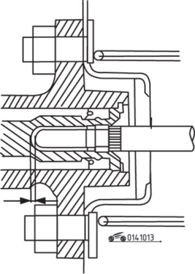
Figure 10.13. Clearance between the primary piston and the brake booster pusher
Theoretically, it is necessary to measure the clearance between the primary piston and the brake booster pushrod (figure 10.13). The manufacturer produces a special tool 49 B002 765 for this purpose. If this tool is not available, use a depth gauge or similar tool to determine the depth of the recess in the primary piston and the protrusion of the vacuum booster pusher. The recommended value without applying vacuum to the booster is 4.06–6.09 mm.
Adjustment is made by rotating the vacuum booster pusher, held in place by a lock nut.
Each time the master cylinder is removed, it is necessary to completely bleed the hydraulic system. The time it takes to bleed the system can be reduced if the master cylinder is filled with fluid and pumped or "test bled" before it is installed on the vehicle. Fill the reservoir with brake fluid and slowly push the piston all the way in using a wooden dowel or a Phillips-head screwdriver. Before releasing the piston, block the brake line connections to prevent air from entering the master cylinder, then release the piston. Repeat the procedure until brake fluid without air bubbles starts to flow from the brake line connections. Be careful not to expose the bottom of the tank while bleeding.
Correctly position the brake master cylinder on the brake booster studs and tighten the brake pipe mounting union nuts with your fingers without distorting them.
Tighten the master cylinder mounting nuts securely.
Tighten the brake pipe union nuts securely and connect the connector to the sensors.