


Contents: Checking and adjusting ⇓ Removal and installation the parking…⇓ Removal and installation the parking…⇓
Checking and adjusting
Pull the parking brake lever and ensure that it is fully engaged between 7 and 9 clicks.
Start the engine, press the brake pedal two or three times and stop the engine.
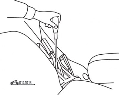
Figure 10.15. Adjusting the parking brake lever travel
Remove the parking brake cover and use a screwdriver to turn the adjusting nut until the lever travel is within the required range (figure 10.15). The parking brake indicator lamp in the instrument cluster should come on after the lever is tightened one click.
Release the parking brake lever and make sure the rear brakes do not slow the vehicle.
Removal and installation the parking brake assembly
Remove the parking brake cover.
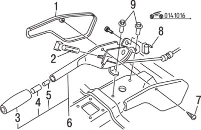
Figure 10.16. Parking brake assembly components: 1 – screw; 2 – adjusting nut; 3 – handle; 4 – button; 5 – return spring; 6 – parking brake unit; 7 – screw; 8 – parking brake indicator lamp switch connector; 9 – bolts
Disconnect the connector from the parking brake indicator switch (figure 10.16).Unscrew the adjusting nut.
Remove the bolts, disconnect the parking brake cable and lift the lever assembly to remove it from the vehicle.
Inspect the ratchet sector and pawl for damage to the teeth and check the elasticity of the return spring. Replace damaged elements with new ones.
Before installation, lubricate the gear sector and ratchet teeth with white lithium-based lubricant.
Installation is carried out in the reverse order of removal.
Adjust the parking brake.
Removal and installation the parking brake drive
Rear cable
Raise the rear of the vehicle and support it securely on stands.
Remove the cable clamp.
Remove the brake shoe assembly and disconnect the cable from the brake shoe actuator lever.
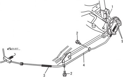
Figure 10.17. Rear parking brake cable: 1 – bracket; 2 – bolt; 3 – adjusting nut; 4 – rear parking brake cable; 5 – cable connector with brake shoe drive lever
Remove the bolts and mounting nut and remove the rear parking brake cable from the vehicle (figure 10.17).
Installation is carried out in the reverse order of removal.
Before installation, apply white lithium-based lubricant to the cable seal ring. After installation, turn the installation nut until the compensator is positioned at a 90° angle to the front parking brake cable.
If necessary, adjust the travel of the parking brake lever.
Front cable
Remove the parking brake lever cover. Unscrew and remove the adjusting nut.
Raise the rear of the vehicle and support it securely on stands.
Remove the front cable from under the vehicle, disconnecting the rear cable from the compensator.
Installation is carried out in the reverse order of removal.
If necessary, adjust the travel of the parking brake lever.