


The brake booster is not designed for repair, so if any malfunctions occur, it must be replaced.
Loosen the nuts securing the master cylinder to the brake booster. Disconnect the brake fluid level sensor connector and move the brake master cylinder aside. Do not kink the brake lines leading to the master cylinder. If there is any doubt about the flexibility of the lines, disconnect them from the master cylinder and plug the ends.
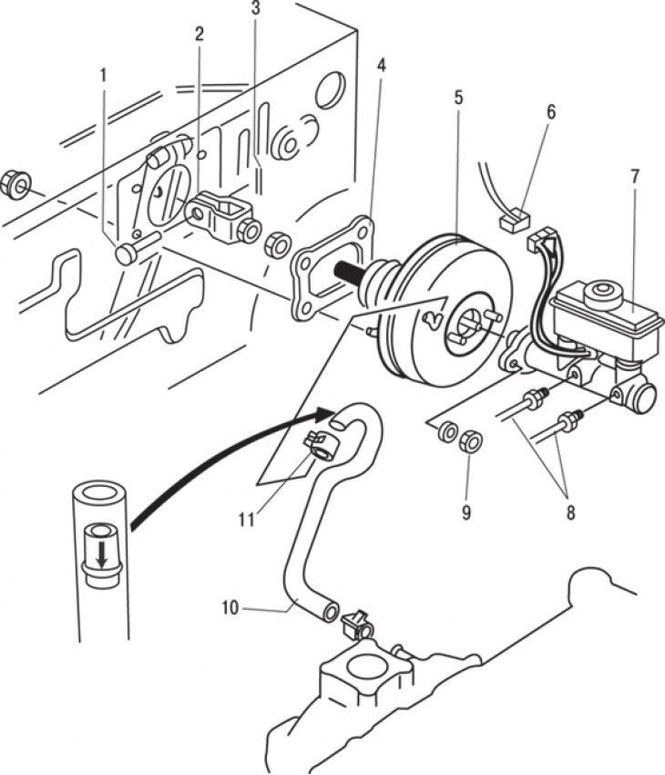
Figure 10.20. Brake booster mounting elements: 1 – pin with a head and a hole for a cotter pin; 2 – fork and nut; 3 – cotter pin; 4 – gasket; 5 – brake booster; 6 – brake fluid level sensor connector; 7 – master brake cylinder; 8 – brake pipes; 9 – nut; 10 – vacuum hose; 11 – clamp
Disconnect the vacuum hose from the front of the brake booster (figure 10.20).
Inside the vehicle, remove the heater fan duct from under the instrument panel and the lower trim. Remove the cotter pin and the pin with a head and a hole for the cotter pin, disconnect the brake booster push rod from the brake pedal. When disconnecting, do not tilt the pusher to the side.
Unscrew the four nuts securing the vacuum booster and carefully remove it from the engine compartment.
If a new brake booster needs to be installed, check the clearance between the primary piston of the master cylinder and the booster pushrod.
When installing, loosely screw on the four nuts and connect the push rod to the brake pedal. Tighten the nuts and connect the vacuum hose. If the hydraulic brake lines have been disconnected, bleed the brake system completely to remove any air that has entered it.
Check the installation height and free play of the brake pedal and adjust them if necessary.