


Raise the front of the vehicle, support it securely on stands and remove both front wheels.
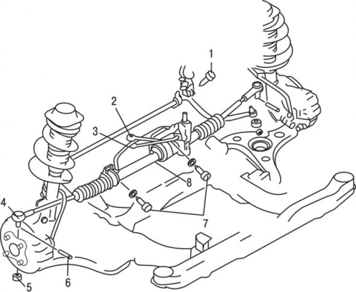
Figure 11.19. Steering gear mounting elements on a vehicle: 1 – tie bolt; 2 – power steering pressure hose; 3 – power steering return hose; 4 – steering rod connected to the steering knuckle; 5 – nut; 6 – cotter pin; 7 – bolt; 8 – steering mechanism
Remove the cotter pins, unscrew the nuts and separate the tie rod ends from the steering knuckles (figure 11.19).
On models equipped with power steering, disconnect the connector from the switch, disconnect the lines and wrap them with a rag to collect any leaking fluid.
Remove the bolts and remove the steering gear through the left wheel arch.
If the steering gear requires repair, there are several possible options for further action. You can purchase a new steering gear and install it as a complete unit, but this is the most expensive option. You can take the removed steering mechanism to a service station for repair. Another option is to carry out the repairs yourself, although this is a difficult operation that requires the use of a press.
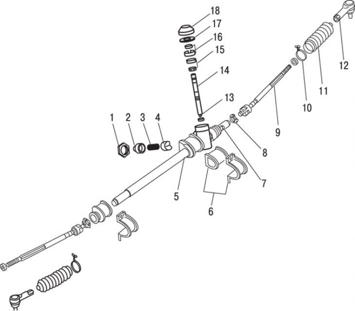
Figure 11.20. Steering gear without power steering: 1 – lock nut; 2 – adjustment plug; 3 – spring; 4 – stop; 5 – steering gear housing; 6 – mounting brackets and bushing; 7 – toothed rack; 8 – washer; 9 – steering rod; 10 – wire clamp; 11 – protective cover; 12 – steering rod end; 13 – lower bearing; 14 – gear shaft; 15 – upper bearing; 16 – rear casing and seal; 17 – lock nut; 18 – dust cap
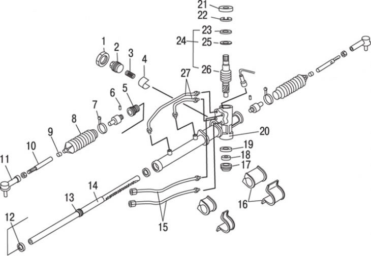
Figure 11.21. Steering gear with power steering: 1 – lock nut; 2 – adjustment plug; 3 – spring; 4 – stop; 5 – rack bushings; 6 – spring pins; 7 – wire clamp; 8 – protective cover; 9 – clamp; 10 – steering rod; 11 – steering rod end; 12, 23 – oil seals; 13 – O-ring seal; 14 – toothed rack; 15 – pipelines and ring seals; 16 – Mounting brackets and fasteners; 17 – gear plug; 18 – lock nut; 19 – bearing; 20 – steering gear housing; 21 – dust cap; 22 – thrust ring; 24 – control valve, seal and bearing; 25 – bearing; 26 – control valve; 27 – pipelines
The main elements of the steering mechanism are shown in the figure 11.20, 11.21.
Installation is carried out in the reverse order of removal. If your model is equipped with power steering, add fluid to the reservoir and bleed air from the system after installing it.
On all models, finally check the front wheel alignment angles and adjust them if necessary.