


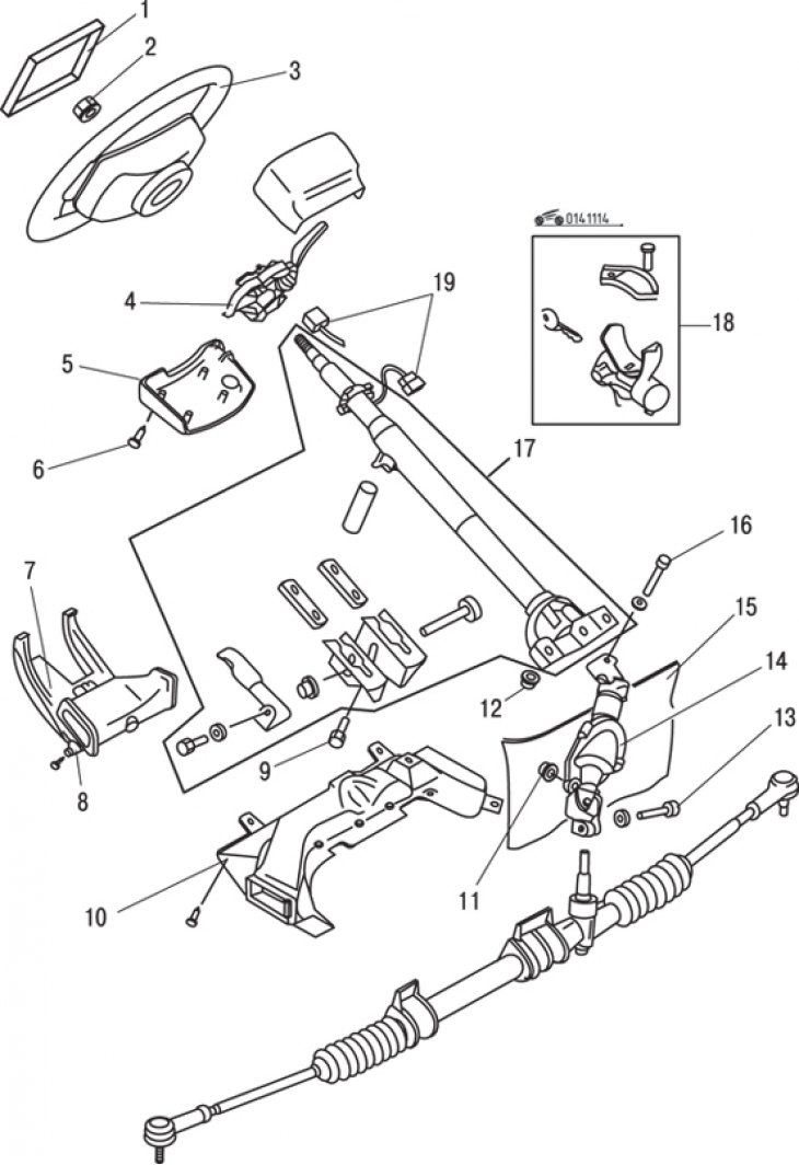
Figure 11.14. Steering: 1 – sound signal button; 2, 11, 12 – nuts; 3 – steering wheel; 4 – combination switch; 5 – steering column cover; 6 – screw; 7 – bottom panel; 8 – screws; 9, 13, 16 – bolts; 10 – air duct; 14 – intermediate shaft; 15 – engine compartment partition; 17 – steering shaft; 18 – steering column lock; 19-pin connectors
All models are equipped with rack and pinion steering, which includes a steering wheel, steering column, intermediate shaft, steering gear, steering rods and steering knuckles (figure 11.14).
The power steering also includes a belt-driven pump to create hydraulic pressure. In non-power steering, the motion from turning the steering wheel is transmitted through the steering column and intermediate shaft to the steering gear pinion shaft. The teeth on the pinion shaft are connected to the teeth of the rack so that when the shaft is turned, the rack moves left or right in the steering gear housing. Attached to each end of the rack are steering rods, which in turn are attached to the steering knuckles on the front wheels. Thus, the force of the rack movement to the right and left is directly the force that turns the wheels.
To reduce the force applied to the steering wheel to turn it, vehicles are equipped with hydraulic power steering. As an additional force, high-pressure working fluid is used, which is supplied to the working cylinders located on the steering gear. The distribution valve is used to pump fluid into the power cylinder under pressure that corresponds to the steering wheel angle. The control valves operate according to the so-called open center principle, i.e. when the control valve is not activated, the fluid supplied by the pump is diverted back to the tank at zero pressure. The pressure in the hydraulic system is created by a pump driven by a belt from the engine crankshaft pulley.
The energy-absorbing steering column folds in the event of a frontal collision to reduce the risk of injury to the driver. The steering column also contains the ignition switch with steering lock, a warning buzzer, and switches for the turn signal, headlights, and windshield wipers. Due to design features (folding) when installing steering column parts, it is important that only the specified screws, bolts and nuts are used and tightened to the specified torques.
In addition to the standard steering column, it is possible to install a column with an adjustable tilt angle.
Technical specifications
- Type - Rack and pinion steering
- Turning radius, m — 5.1
Tightening torques, Nm
| Tie rod end fastening nut | 30–45 |
| Intermediate shaft mounting nut | 18–27 |
| Fastening the steering gear to the body | 32–47 |
| Steering wheel mounting nut | 40–50 |
| Steering column bracket mounting nuts/bolts | 16–23 |
| Wheel mounting nuts | 90–120 |
[The article is reprinted from the portal: Mazbook.ru]